
📷 IMAGE AREA — M70/M700 alarm screen: alarm group, axis and full message (M01 / T01 / S03 / P)
Recommended size: 1200×630 px (16:9, hero) · WebP/JPG · <150 KB · filename: mitsubishi-m70-alarm-screen.webp · alt: Mitsubishi M70 M700 alarm screen M01 T01 S03 P alarm groups
Alarms on the Mitsubishi M70 and M700 controls do not come from a single group. The letter and number at the start of the on-screen code help identify which system the fault comes from. This guide covers the groups an operator or maintenance person is most likely to meet on vertical machining centers: M-code operation alarms, T-code stop/start-inhibit messages, S01/S03/S04 servo-drive alarms, P-code program errors and reference, limit, overload, temperature, communication and collision alarms. The source manual’s descriptions are preserved and simplified.
1. How is the alarm code structure read?
On screen, for example M01 S/W stroke end axis exists 0007 has three parts: M01 the alarm group, S/W stroke end axis exists the description, 0007 the alarm number. On a servo alarm, e.g. S03 Overload 1 : NR 0050 X — S03 servo/spindle group, Overload 1 the overload alarm, NR the reset class, 0050 the detailed number, X the axis where the alarm occurred. When evaluating an alarm, do not look only at the number; read the leading group, the axis and the full description together.
2. First actions when an alarm appears
When an alarm occurs, changing a parameter directly is not correct. First: note the full alarm code, record which axis it occurred on and which line the program stopped on, look at the tool/axis position and whether there is a jam, check whether the override switches are at zero, check conditions like emergency stop/door/lubrication/air pressure, reset the alarm only after the cause is understood, do not force the machine if it recurs, and inform authorized maintenance for drive/electrical alarms. Especially for servo, spindle, overcurrent, grounding and power-module alarms, continuing to run by resetting repeatedly can cause bigger drive/motor faults.
3. M01 operation alarms
M01 alarms are usually caused by axis motion, reference return, limit, interlock, spindle conditions or panel settings.
- M01 0001 — Dog Overrun: during reference return the axis passed the near-point limit switch/reference dog area and the reference signal was not detected where expected. Causes: short dog, high return speed, late sensor detection, cable/mechanical dog problem. Solution: increase the reference dog length, reduce the return speed; move the axis away from the reference area and check the sensor, then retry.
- M01 0002 — Some Axis Does Not Pass Z Phase: on the first reference return an axis could not pass the encoder Z phase. Solution: move the axis opposite the reference direction by at least one detector turn and repeat the reference. If it recurs every power-on, the encoder/Z phase/cable must be checked by technical service.
- M01 0003 — Reference Point Direction Illegal: in manual reference return the selected direction does not match the reference return direction. Solution: move the axis in the correct reference direction (+/−); the alarm cancels with the correct direction.
- M01 0004 — External Interlock Axis Exists: the external interlock (safety lock) is active and an axis is in a motion lock. Causes: door open, magazine not in position, pallet not ready, low hydraulic/pneumatic pressure, lubrication incomplete, PLC input signal missing, broken line. Operator: release the E-stop, close the doors, check air/hydraulic pressure, see if the magazine is at home. If it persists, PLC inputs/wiring is a service job.
- M01 0005 — Internal Interlock Axis Exists: a motion lock inside the CNC. No single cause: Servo OFF active, wrong command on a removable axis, command in the manual skip direction, manual/automatic simultaneous-motion conflict, absolute-position start needed, manual speed command while the tool-length-measure signal is on. Solution: check the Servo OFF state, the probe/measure function, the manual/automatic selection; solve an absolute-position alarm first if present.
- M01 0006 — H/W Stroke End Axis Exists: the axis reached the hardware stroke-end limit (physical switch). Solution: move the axis away from the limit at low speed in JOG/HANDLE opposite the limit direction, check the stroke-end line/switch. Do not command the wrong direction while the limit-release button is pressed.
- M01 0007 — S/W Stroke End Axis Exists: the axis reached the software motion limit (not physical, the software limit stored in the CNC). Causes: a command beyond the limit, wrong G54–G59, wrong tool length, G90/G91 mix-up, wrong limit parameter. Check: which axis, the coordinate on the stopped line, G90/G91, G54–G59, the H value. If the axis is not near the real limit, a zero/offset error is likely.
- M01 0009 — Reference Point Return Number Invalid: a second reference command was given before the first reference return was complete. Solution: complete the first reference return first, then run G30/other reference commands.
- M01 0102 — Cutting Override Zero: the cutting-feed override switch is at 0; the program cannot move to feed. Solution: set Feed Override to a non-zero (low for the first test) value. If it persists while the switch is not at zero, there may be a signal-line/PLC problem.
- M01 0103 — External Feed Rate Zero: in JOG or dry run the manual feed switch is at zero. Solution: set the manual feed rate to non-zero; if not, check the panel signal/PLC input.
- M01 0105 — Spindle Stop: the spindle is stopped during a synchronous-feed/spindle-linked command. Causes: spindle not started, M03/M04 missing, encoder signal not received, faulty encoder cable, wrong program. Solution: rotate the spindle; use dry run if not cutting; check the encoder cable/pulse and correct the program.
- M01 0111 — Restart Switch ON: the mode was switched to manual before the restart search completed, or the restart switch was left on. Solution: search the restart block, turn off the switch, do not change mode before the search finishes.
- M01 0125 — Rapid Override Zero: the rapid override switch is at 0. Solution: set Rapid Override to non-zero (1%, 5% or the lowest safe rate).
- M01 0126 — Program Restart Machine Lock: machine lock was applied to the axis returning to the restart position. Solution: turn off machine lock and restart the restart operation.
- M01 0128 — Restart Position Return Incomplete: automatic start was given before the axis reached the restart position. Solution: move the axis manually to the restart position; if automatic restart return is used, the relevant setting must be active. Do not give cycle start before verifying the axes are safe.
4. T01, T02, T03 stop codes
T-code messages are not always a serious fault; they often explain why the CNC does not start automatic operation or why it stopped.
- T01 0101 — Axis in Motion: an axis is still moving. Solution: wait for all axes to stop and give cycle start again.
- T01 0102 — NC Not Ready: the NC is not ready for automatic operation; usually another alarm is in the background. Solution: check the alarm history/active list and clear the other alarm first.
- T01 0103 — Reset Signal ON: the reset signal is continuously on. Solution: check the reset button is not stuck; if not, the button/cable/PLC sequence is checked.
- T01 0104 — Auto Operation Pause Signal ON: the Feed Hold signal is active. Solution: check the Feed Hold button (may be stuck); the cable/PLC signal is checked.
- T01 0105 / 0106 — Hardware / Software Stroke End: an axis is at the physical or software stroke limit. Solution: move the axis manually away from the limit; for software, program/zero/tool offset is checked.
- T01 0107 — No Operation Mode: no automatic operation mode is selected. Solution: select AUTO/MEMORY; if it persists while selected, the mode switch/signal line is checked.
- T01 0108 — Operation Mode Duplicated: more than one automatic mode appears selected at once. Solution: set the mode switch to one position; a contact/PLC short is checked.
- T01 0109 — Operation Mode Changed: the mode was changed during automatic operation. Solution: return to the previous mode and give cycle start.
- T01 0112 — Restart Position Return Incomplete: the axis did not return to the restart position. Solution: move the axis manually to the restart position; if automatic return is used, the relevant function must be active.
- T01 0113 — CNC Overheat: the control temperature exceeded the limit. Causes: clogged cabinet filter, non-running fan, faulty A/C/cooler, high ambient, unsuitable air channels. Solution: cool the unit, check fan/filter, do not force the machine before lowering the temperature.
- T01 0116 — Cycle Start Prohibit, Battery Alarm: the NC battery voltage has dropped. Solution: replace the battery per the service procedure. On machines that must keep control power during replacement, do not cut power at random (absolute position/system data can be lost).
- T02 0203 — Reset Signal ON: reset was given while the program ran, and the execution position returned to the start. Solution: run the program from the start or apply a safe restart procedure.
- T02 0204 — Auto Operation Pause Signal ON: Feed Hold is active, the program waits. Solution: if conditions are safe, resume with cycle start.
- T03 0301 — Single Block Stop Signal ON: Single Block is on, the program stops after each block. Solution: for single-block work, give cycle start after each line; for continuous work, turn off Single Block.
📷 IMAGE AREA — Servo/spindle drive (S01/S03) diagnostic screen and axis LED/status view
Recommended size: 1000×750 px (4:3, in-content) · WebP/JPG · <150 KB · filename: mitsubishi-m70-servo-drive-alarm.webp · alt: Mitsubishi M70 servo drive S01 S03 alarm diagnostic screen
5. S01 servo/spindle drive initialization and setup alarms
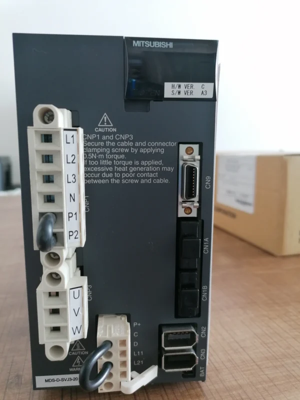
S01 alarms usually appear at power-up or drive initialization: drive not ready, parameter/setup error, communication or hardware self-check faults. Most S01/S02/S03 alarms are drive/electrical and, except for simple operator checks, are the maintenance/service team’s job. Repeated resetting without fixing the cause can damage the drive/motor.
- S01 0010 — Insufficient voltage: the drive main-circuit DC bus voltage dropped below the limit. Causes: low/interrupted mains, phase loss, weak main contactor/relay, power-module problem. Operator: check the mains voltage and that all phases are present. The rest is a service job.
- S01 0011 — Axis selection error: the drive axis-number/rotary-switch setting is wrong or duplicated. Solution: the drive axis-number setting must be corrected by service; the operator does not intervene.
- S01 0012 — Memory / hardware error: a fault was detected in the drive’s internal memory/hardware self-check. Solution: power-cycle once; if it recurs, the drive is checked/replaced by service.
- S01 0013 — Software processing error: an internal software/processing timing error in the drive. Solution: power off and on; on repetition service checks the firmware/hardware.
- S01 0016 — Magnetic pole position / detector error: the motor magnetic-pole position or detector signal could not be read correctly. Causes: encoder cable, connector, shielding/grounding, detector fault. Solution: service checks the encoder cable and connections.
- S01 0017 — A/D converter error: a fault in the drive’s internal current/voltage measurement (A/D) circuit. Solution: a hardware fault; the drive is checked by service.
- S01 0018 — Motor/detector combination error: the connected motor or detector does not match the drive parameters. Causes: wrong parameter after a motor/encoder change, wrong cabling. Solution: service checks motor-drive matching and the parameters.
- S01 001A — Detector communication error: serial communication with the encoder/detector is broken. Causes: cable break, connector, noise, faulty detector. Solution: service checks the encoder cable, connectors and grounding.
- S01 001B — Detector count/feedback error: the position feedback pulse from the detector is inconsistent. Solution: cable/noise/detector are checked by service.
6. S03 servo alarms (overload, overcurrent, overvoltage, overheat)
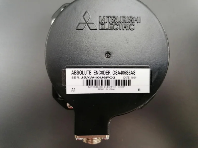
S03 alarms are the most attention-worthy group in terms of motor and drive protection. They usually occur while running and stop the machine to prevent the motor/drive being damaged. The reset class (NR/AR/PR) is important: NR resettable, AR needs power-cycle, PR fixed after cause removed. Do not repeatedly reset and force these alarms.
- S03 0030 — Over regeneration: the regenerative energy from the motor during deceleration exceeded the resistor’s capacity. Causes: too-frequent accel/decel, heavy load, resistor/cooling problem, wrong parameter. Solution: service checks the regen resistor and cooling; the machining cycle/accel-decel is reviewed.
- S03 0031 — Overspeed: the motor exceeded the allowed speed limit. Causes: parameter, feedback error, mechanical drive-away. Solution: service checks the feedback/parameter; the operator does not force the machine.
- S03 0032 — Power module overcurrent: excessive current in the drive power module. Causes: short, grounding, motor/cable fault, mechanical jam. Important: do not repeatedly reset; a serious drive fault is possible. Solution: service checks the motor, cable and power module.
- S03 0033 — Overvoltage: the main-circuit DC bus voltage rose above the limit. Causes: high mains, regen problem, deceleration energy. Solution: service checks the mains and the regen circuit.
- S03 0034 — Communication (NC-drive) CRC error: a data error in the NC–drive communication. Causes: cable, connector, noise, grounding. Solution: service checks the communication cable and connections.
- S03 0035 — Communication data error: the data received by the drive is out of range. Solution: communication line/parameter is checked by service.
- S03 0036 — Communication interrupted: NC–drive communication was completely lost. Causes: broken cable, loose connector, drive power. Solution: service checks the connections and drive power.
- S03 0037 — Parameter error: a value out of range in the drive parameters. Causes: wrong parameter, data loss, wrong setup after change. Solution: service checks/reloads the drive parameters.
- S03 003A — Overcurrent (instantaneous): an instantaneous excessive current in the drive. Causes: short, grounding, mechanical jam. Solution: do not force; service checks the motor/cable/module.
- S03 003B — Power module overheat: the power-module temperature exceeded the limit. Causes: clogged cooling fan/filter, high ambient, continuous heavy load. Solution: check the cooling; service intervenes for the module.
- S03 0046 — Motor overheat: the motor or the thermal sensor in it reported overtemperature. Causes: continuous overload, cooling problem, faulty sensor/cable. Solution: reduce the load, allow cooling; service checks the sensor/cabling.
- S03 0050 — Overload 1: the motor drew current above the limit for too long (thermal overload). Causes: excessive cutting, blunt tool, mechanical jam/tightness, wrong parameter. Solution: reduce cutting values, check the tool, look for a mechanical jam; the operator can do the first checks here.
- S03 0051 — Overload 2: a short but very high overload current. Causes: sudden jam, collision, mechanical lock. Solution: check whether there was a collision/jam; do not restart before removing the cause.
7. S04 spindle drive alarms
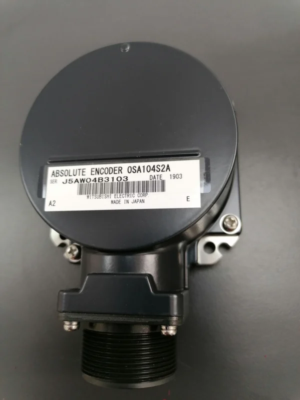
S04 alarms concern the spindle motor and its drive. As with servo, most are electrical/drive faults; the operator should do the first checks and call service for the rest.
- S04 spindle overload: the spindle drew current over the limit for too long. Causes: too-heavy cutting, blunt/wrong tool, mechanical tightness at the spindle, cooling problem. Solution: reduce cutting values, check the tool, look for spindle tightness.
- S04 spindle overspeed: the spindle exceeded the allowed speed. Causes: program S value, parameter, feedback error. Solution: check the S command and the parameter; service checks the feedback.
- S04 spindle overcurrent / power module: excessive current in the spindle drive. Causes: short, grounding, motor/cable fault. Solution: do not force; service checks motor, cable and module.
- S04 spindle overheat: the spindle motor or drive overheated. Causes: continuous heavy load, clogged cooling, high ambient. Solution: allow cooling, check the cooling system.
- S04 spindle encoder / orientation error: the spindle encoder signal or orientation (spindle stop at a fixed angle for tool change) failed. Causes: encoder cable, connector, parameter, mechanical. Solution: service checks the encoder and the orientation parameter. If tool change stops without orientation, this alarm should be suspected.
8. P program errors (P alarms)
P alarms report an error in the program the CNC reads. They are usually caused by writing/syntax, missing address or cycle setup, and can be fixed by the operator/programmer.
- P10 — Number of axis addresses over: too many axis addresses in one block, or the same axis written twice (e.g. two X’s). Solution: correct the line, remove the repeated axis.
- P11 — Address error: an invalid/unrecognized address character. Causes: mistyped letter, misplaced sign, wrong character. Solution: correct the address on the line.
- P20 — Division error: a mathematically invalid operation such as division by zero. Solution: fix the value/variable causing the error in the calculation/macro.
- P32 — Address illegal: an address not valid for the current mode/function. Solution: check the mode and the G/M code; remove or correct the wrong address.
- P33 — Format error: the block format is not as expected. Causes: missing address, out-of-order values, missing/extra sign. Solution: rewrite the line to the correct format.
- P34 — G-code error: an unsupported or wrongly-used G code. Solution: check the G code and its parameters; use the correct code.
- P35 — Setting value range over: a value out of the allowed range. Causes: too-large feed/speed/coordinate, wrong unit. Solution: bring the value into range.
- P36 — Program end error: no correct program end (M02/M30) or a missing end block. Solution: add the correct end code to the program.
- P37 — O-number / sequence-number zero: a program or sequence number was written as 0 or is invalid. Solution: give a valid program/line number.
- P39 — No specified program / program not found: the called program/subprogram was not found. Causes: wrong number, program not in memory, misspelled call. Solution: check the program number, load the missing subprogram.
- P430 — Reference return incomplete: a command requiring reference return was given, but reference return is not complete. Solution: complete reference return first, then run the program.
- P600–P608 — Compensation / cycle / setup errors: cutter-radius compensation (G41/G42), fixed-cycle or coordinate-setup errors. Causes: compensation not cancelled (G40), wrong H/D number, missing cycle parameter, wrong plane (G17/G18/G19). Solution: check the compensation start/cancel, the H/D value, the cycle parameters and the plane selection; correct the program.
9. Restart and safe continuation after an alarm
After the alarm cause is removed, the machine should not be started carelessly. First reset the alarm and confirm it does not recur. If the program stopped mid-way, use the correct restart/block-search procedure to reach the right line instead of running from the top with the tool possibly in the material. Bring the axes to a safe position, verify the spindle and coolant conditions, and give the first cycle start at low rapid and feed override. If the same alarm returns immediately, do not force it — investigate the cause or call service.
10. Alarms the operator can usually fix
The following group is usually solvable without service, with panel settings or simple checks: override switches at zero (M01 0102/0103/0125), Feed Hold/Single Block/reset stuck (T01 0104/T03 0301/T01 0103), spindle not started (M01 0105), reference direction/order (M01 0003/0009), software limit / zero-offset errors (M01 0007), restart-position mistakes (M01 0111/0126/0128), and P program-writing errors (P10/P11/P33/P34/P35/P36/P39). Here, understanding the cause and correcting the program/setting is enough.
11. Alarms that need service / maintenance
Most S01/S03/S04 drive alarms (overcurrent, overvoltage, power-module, communication, encoder, magnetic-pole, A/D errors), CNC overheat (T01 0113), battery alarm (T01 0116) and hardware/memory errors should be handled by authorized maintenance. In these, do not repeatedly reset, do not change parameters at random, and do not force the machine. Especially in overcurrent/grounding/power-module alarms, running by resetting can cause bigger drive and motor faults. Note the alarm code, the axis and the conditions and pass them to service.
12. Quick alarm reference table
| Code | Meaning | First action |
|---|---|---|
| M01 0001 | Reference dog overrun | Lengthen dog, lower speed, retry |
| M01 0004 | External interlock | Door/pressure/magazine check |
| M01 0006 | Hardware stroke end | Move axis away from limit |
| M01 0007 | Software stroke end | Check zero/offset/program |
| M01 0102/0125 | Override zero | Set feed/rapid override |
| M01 0105 | Spindle stopped | Start spindle / check encoder |
| T01 0113 | CNC overheat | Cooling, fan/filter, service |
| T01 0116 | Battery alarm | Service battery procedure |
| S03 0032/003A | Overcurrent | Do not reset; call service |
| S03 0050/0051 | Overload | Reduce cutting, check jam/tool |
| S03 0046 | Motor overheat | Reduce load, cooling, service |
| S04 | Spindle drive alarm | Check cutting/cooling; service |
| P10/P11/P33 | Program writing error | Correct the line |
| P430 | Reference incomplete | Complete reference return |
| P600–P608 | Compensation/cycle error | Check G40/H-D/plane |
Conclusion
On the Mitsubishi M70/M700 the alarm code is not just a number: the leading letter-group (M/T/S/P), the axis and the description together point to the cause. M01 and T operation alarms are usually solvable by the operator with settings and simple checks; P alarms with program corrections. S01/S03/S04 drive alarms concern motor and drive protection and, except for the first checks, are the maintenance team’s job. In every case, understanding the cause instead of blindly resetting is the safest and the least costly approach.
⚠️ Mentor CNC — safety note: The alarm codes, causes and solutions here are general reference information and may vary by machine model, drive type and manufacturer configuration. For servo, spindle, overcurrent, grounding and power-module alarms, do not run the machine by repeatedly resetting; get support from authorized maintenance. Always take your machine’s original Mitsubishi alarm/maintenance manual as the basis. Cut the machine’s power and follow the safety procedures before intervening.