
📷 IMAGE AREA — FANUC Series 0 control panel: DGNOS/PARAM screen, PWE and bit-type parameter entry
Recommended size: 1200×630 px (16:9, hero) · WebP/JPG · <150 KB · filename: fanuc-series-0-parameter-screen.webp · alt: FANUC Series 0 00 0-Mate machining center parameter screen PWE bit entry
The most fundamental factor determining a CNC machining center’s capacity, speed, accuracy and cycle efficiency is the parameters running in the background of the control. This technical guide brings the critical system parameters, axis configurations and operational settings of the FANUC Series 0-MC, 0-MF, 0-GSC, 00-MC, 00-GSC and O-Mate MC/MF machining center units together in one source for operators and engineers. The parameters are explained category by category, with bit details. Some functions can depend on the control option, the software version and the machine builder’s PMC implementation.
Part 1: Step-by-step parameter change procedure for operators
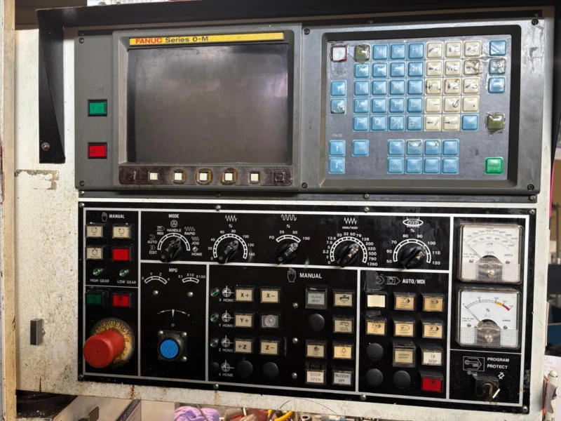
To change parameters safely and correctly on FANUC Series 0 units, apply the following steps in order:
- Mode selection: Select
MDImode from the control panel. - Screen change: Press the
[DGNOS/PARAM]function button to display the parameter setting screen. - Unlocking write (PWE): Type
No.on the address line with 0 next to it and press[INPUT]; on the setting screen, set PWE (Parameter Write Enable) to 1. PWE=1 removes the parameter protection and allows data writing. - Parameter search: Type
No.then the parameter number (e.g. 0531) and press[INPUT]; the screen scrolls to that parameter. - Bit-type entry: Bit parameters are an 8-bit row (Bit 7 leftmost/highest, Bit 0 rightmost/lowest). On Series 0 you cannot change a single bit independently; all 8 bits are entered at once as a string. E.g. with current data
00001000, to set Bit 7 to 1 type10001000. If you type fewer digits, the system treats the rest as 0. - Numeric entry: For integer or micron parameters, type the value in the valid range and press
[INPUT]. - Re-locking: When done, set PWE back to 0.
Critical warning (POWER OFF alarms): If the changed parameter affects permanent hardware or axis settings, the system gives a P/S 000 (Turn off the power) alarm the moment data is entered. In this case, the CNC unit’s main power must be cut and turned on again so the parameters are fully written to memory.
Part 2: System parameters, category by category
Category 1: General setup and setting parameters
Parameter 0000 (bit layout):
- REVX, REVY, REV4: X, Y and 4th axis mirror image. When mirroring is on, axis motion reverses in automatic operation (except reference return); no effect in manual operation.
- TVON: TV (Tape Vertical Parity) check when saving a program. When 1, if the character count in any block is odd, alarm
P/S 002triggers. - ISO: Program output code (1: ISO, 0: EIA).
- INCH: Smallest input increment (1: inch, 0: metric).
- ABS: MDI commands processed incrementally (0) or absolutely (1) — independent of G90/G91.
- SEQ: Automatic addition of sequence numbers (1: automatic).
- TAPEF: Tape format conversion (1: F10/F11 format, 0: standard FS0).
Category 2: Reader/Punch interface and communication
- 0000 (I/O selection): Active channel (0: channel 1 [0002/0552], 1: channel 1 alt [0012/0553], 2: channel 2 [0050/0250], 3: channel 3 [0051/0251]).
- 0002/0012/0050/0051 (#0 STP2): Stop bit (1: 2 bits, 0: 1 bit).
- 0002/0012 (#2 ASR33): 1: 20-mA current-loop interface; 0: FANUC PPR/cassette/portable tape reader.
- 0002/0012/0050/0051 (#3 RSASCI): Program input ASCII (1) or ISO/EIA (0) code.
- 0002/0012/0050/0051 (#7 NFED): Prevents (1) or adds (0) the feed character at block start/end on output.
- 0051 (#1 PARTY): Parity bit on remote buffer/comm line (1: present, 0: none).
- 0051 (#2 SYNAK): SYN/NAK code output control in protocol B. #4 NCKCD: disable CD (signal quality) monitoring in remote buffer (1). #5 ECKL: remote buffer baud clock (internal/external).
- 0055 (#0 ASCII): Non-NC data transfer ISO (0) or ASCII (1). #1 ETX: end code (1: ETX, 0: CR). #2 PROTCA: protocol (1: A, 0: B). #3 RS42: interface (1: RS-422, 0: RS-232C).
- 0070 (#7 ICR): EOB format in ISO output (1: LF, 0: LF/CR/CR). 0075 (#7 IONUL): null-character alarm in EIA (1: alarm).
- 0391 (#6 RS23BN): Not using DC codes (DC1-DC4) for RS-232C flow control (1).
- 0396 (#0 BCC / #2 NCKER / #3 ERCODE): BCC check, ER/TR serial signal check, and adding a 4-digit hex error code to NAK messages.
- 0250 (BRATE2) / 0251 (BRATE3) / 0552 (BRATE0) / 0553 (BRATE1): Channel baud-rate indexes (e.g. 11 = 9600 bps, 12 = 19200 bps; channel 3 max. 921600 bps).
Category 3: Controlled axes and increment system
- 0001 (#0 SCW): Least command increment (output system) on linear axes — 1: inch, 0: metric. Power off after change. 7001 (#0 SCWS): same for 5th/6th axes.
- 0003 (#0–#3 ZMX/ZMY/ZMZ/ZM4): X/Y/Z/4th axis reference return direction and power-on initial backlash direction (1: minus, 0: plus). 7003 (#0/#1 ZM5/ZM6): 5th/6th axis direction.
- 0008 (#2–#4 ADW0/ADW1/ADW2): 4th axis naming (A, B, C, U, V, W). 0280 (AXS4D): 4th axis name character code (when 0030 #6 active).
- 0011 (#2 ADLN): 4th axis linear (1) or rotary (0). Linear brings restrictions in circular interpolation and tool compensation. 7032 (#0/#1 ROT5/ROT6): 5th/6th axis rotary (1)/linear (0).
- 0024 (#1 LII10): Input/output resolution system — 1: IS-A (0.01 mm / 0.001 in), 0: IS-B (0.001 mm / 0.0001 in).
- 0049 (#4 S3JOG): Max. axes moving at once in JOG (1: 3 axes, 0: 1 axis).
- 0057 (#3 MIC): When the decimal point is omitted, whether the value is multiplied by the smallest unit or by 10.
- 0062 (#7 C8NG): 8th axis active (0)/inactive (1).
- 0076 (#1 JZRN): Enables dogless reference return on all axes (1). 0391 (#0–#5 JZRNX-8): dogless reference per axis (0: usable, 1: not usable).
- 0398 (#1 ROAX): Roll-over on rotary axis (reset after 360°). #2 RODRC: in ABS command, shortest way (0) or per sign (1). #3 ROCNT: relative-coordinate rounding.
Category 4: Coordinate systems and offset (G54–G59)
- 0010 (#7 APRS) / 7010 (#7 APRSS): Automatic setup of the workpiece coordinate system (G54–G59) on manual reference return (1: set).
- 0024 (#6 CLCL): Cancel the local coordinate system (G52) after reference return (1) or keep it (0).
- 0028 (#5 EX10D): External workpiece shift value applied directly (0) or 10× (1).
- 0708–0711 (PRSX–PRS4): Reference coordinates in automatic coordinate setup for X/Y/Z/4th axis (unit 0.001 mm). 0815–0818 (PRSTIX–PRSTI4): in inch mode (0063 #2 PRSTIN=1).
- 0751–0754 (EXOFS1–EXOFS4): Common external work zero point offset shift.
- 0755–0758: G54 · 0759–0762: G55 · 0763–0766: G56 · 0767–0770: G57 · 0771–0774: G58 · 0775–0778: G59 zero point offset values.
Category 5: Stored stroke limits
- 0008 (#6 OTZN): Z axis stored stroke limit check (1: disable, 0: enforce).
- 0015 (#4 LM2): Hardware 2nd stroke limit switching signal (EXLM2) enabled (1).
- 0024 (#4 INOUT): On the 2nd stroke limit, forbidden zone inside (0) or outside (1) the limits.
- 0065 (#3 PSOT): Software stroke check before first reference at power-on (0: do, 1: defer until first reference).
- 0076 (#7 OTRFOM): Alarm triggered just before the limit is exceeded (1) or when exceeded (0).
- 0700–0703 / 0704–0707 (LT1): X/Y/Z/4th axis plus and minus 1st software stroke limits (distance from reference). 0743–0746 / 0747–0750 (LT2): 2nd stroke limits when LM2=1.
Category 6: Axis feedrates and override
- 0001 (#6 RDRN) / 7001 (#6 RDRNS): Dry Run enabled on G00 commands (1).
- 0008 (#5 ROVE): Disable rapid override signal (ROV2) (1). 0010 (#0 ISOT): allow manual rapid without reference (1).
- 0011 (#3 ADNW): Feedrate type (1: Type B — rotary axis JOG speeds independent via 0565/0566; 0: Type A).
- 0015 (#3 SKPF): Use of dry run/override/auto acc-dec during G31 skip (1).
- 0393 (#1 COVOUT): Auto corner override also valid on outer-arc machining (1). #4 HLCFCLMP: clamp linear-axis cutting speed to max cutting speed in helical interpolation (1). #5 STOVO: full axis stop when override is 0% in rapid (1).
- 0397 (#2 OVR255): Fine feedrate override control in 1% steps (1).
- 0213 (AOVMDR): Min. deceleration ratio on inner circular cuts in auto corner override (factory 1%). 0214 (AOVOR): inner-corner override reduction (factory 50%). 0215 (AOVTH): inner-corner decision angle (1–1799, standard 91).
- 0518–0521 (RPDF): X/Y/Z/4th axis max rapid rates (mm/min). 7518/7519: 5th/6th axis. 0527 (FEDMX): max cutting feed. 0530 (FEDFL): cutting base speed on the exponential curve (FL). 0533 (RPDFL): F0 safety base speed. 0534 (ZRNFL): reference-return slow approach speed.
- 0559–0562 (RPDJ): JOG speeds. 0565 (JOGF): Type B JOG constant. 0580 (AOVLE) / 0581 (AOVLS): corner override deceleration start/end distances.
Category 7: Acceleration/deceleration and corner control
- 0020 (#5 NCIPS): Skip in-position check on deceleration (1: skip, 0: check).
- 0045 (#3 LSUP): Post-interpolation acc-dec type in cutting (1: linear, 0: exponential). #4 CCINP: cutting in-position tolerance from separate parameters (1: 0609–0612).
- 0048 (#4 SMZCT): Transition smoothing between G00 blocks (block overlap) enabled (1).
- 0393 (#0 FERDT): Auto corner deceleration/geometry protection (1: active). 0395 (#3 CHEAFD): advanced corner control based on feedrate difference between blocks (1).
- 0399 (#2 RPDFF): Feed Forward applied only to cutting (0) or cutting+rapid (1).
- 0379: In block overlap, at what percent of the current speed the next block starts (0%–100%).
- 0522–0525 (LINT): X/Y/Z/4th axis G00 linear acc-dec time constants (msec). 0529 (FEEDT): cutting/manual exponential acc-dec time constant (msec).
📷 IMAGE AREA — Servo parameter screen: CMR/DMR, loop gain, in-position and backlash values
Recommended size: 1000×750 px (4:3, in-content) · WebP/JPG · <150 KB · filename: fanuc-series-0-servo-parameter.webp · alt: FANUC Series 0 servo parameter CMR DMR loop gain backlash
Category 8: Servo motor and accuracy tolerance
- 0004–0007 (GRDX–GRD4): X/Y/Z/4th axis Reference Counter capacities — reference accuracy via the grid method.
- 0004–0007 (DMRX–DMR4): Detection Multiplication Ratio — position feedback resolution; coded from the manual table per digital/analog servo type.
- 0021 (#0–#5 APCX–APC8): Absolute Pulse Coder present (1: yes). 0022 (#0–#5 ABSX–ABS8): absolute reference fixed in memory (1: fixed); reset on reader change.
- 0100–0103 (CMRX–CMR4): Command Multiplication Ratios — ratio of CNC pulses to motor step.
- 0500–0503 (INPX–INP4): In-position width. 0504–0507 (SERRX–SERR4): max allowed position error during travel; if exceeded, servo alarm.
- 0507–0511: Grid Shift amounts. 0512–0515: position loop gain (standard 3000).
- 0535–0538 (BKLX–BKL4): X/Y/Z/4th axis backlash compensation. 0593–0596 (STPEX–STPE4): position error limit at a stop. 0609–0612: independent cutting in-position tolerance when CCINP=1.
Category 9: Spindle control
- 0003 (#5 GST): On SOR signal, gear change (1) or orientation (0). 0013 (#5 ORCW): S analog voltage polarity in orientation. 0013 (#6/#7 TCW/CWM): M03/M04 analog voltage sign combination.
- 0014 (#0 SCTA): Spindle speed arrival (SAR) checked continuously during cutting (1) or only at start (0). 0024 (#2 SCTO): SAR signal check (1: check).
- 0028 (#6/#7 PSG): Spindle–position coder gear ratio multipliers. 0108 (SPLOW): stable speed during gear change. 0110 (SCTTIM): delay before speed-signal check after S command (msec).
- 0539 (GRHMAX) / 0541 (GRLMAX): Max speed in high/low gear (RPM). 0540 (GRHMIN): min speed base in tapping.
- 0542 (SPDMAX) / 0543 (SPDMIN): Max/min analog voltage to spindle drive (max 4095). 0551 (LOWSP): min speed in G96. 0556 (SCLMP): max speed clamp in G96.
Category 10: Tool offset and compensation
- 0001 (#3 RS43): On RESET, keep (1) or clear (0) the active G43/G44 tool length compensation vector.
- 0003 (#6 TSLT): Tool length compensation axis — 0: always Z (Type A), 1: axis perpendicular to the selected plane (Type B).
- 0016 (#2 SUPM): Cutter comp. C start-up/cancel mechanism (0: Type A, 1: Type B). 0019 (#3 TLCD): tool length compensation memory type (A/B/C).
- 0030 (#2 OFCDH): Tool compensation memory C active (1) — 0036 #6 must also be 1. 0036 (#6 OFRD): 1: length comp. called by H, radius comp. by D independently; 0: both by H.
- 0397 (#3 NOPS41): Disable interference (profile overlap) check while cutter comp. is on (1). 0557 (CRCDL): min linear move that can be ignored on narrow outer corners (0.001 mm).
Category 11: Canned cycles and drilling
- 0002 (#4/#5 PMXY1/PMXY2): In G76/G87, the tool shift axis/direction after orientation at the hole bottom (per G17/G18/G19: +X, -X, +Y, -Y, etc.).
- 0012 (#4 FXCS): In G74/G84, spindle reverse at hole bottom without waiting for M05 (1). #5 FXCO: in G76/G87, oriented spindle stop without M05 (1).
- 0057 (#6 FXY): Drilling axis always Z (0) or the active axis (1).
- 0531 (CYCR): Relief amount in G73 high-speed pecking (0.001 mm). 0532 (CYCD): cutting start point clearance in G83 pecking.
Category 12: Rigid tapping (advanced)
- 0035 (#5 RGCTO): In rigid tapping, allow the pulling-out acc-dec time constant to differ from the entry one (1: independent of 0400–0402).
- 0063 (#4 RGDOV): Feedrate override switch active during retract (1).
- 0076 (#3 G84RGD): G84/G74 recognized directly as rigid tapping code (when 1, no M29 needed before the cycle).
- 0378: Retract speed multiplier when RGDOV=1. 0388 (#0 PCTPH): in pecking rigid mode, Z returns to the R safety plane (1) or to the previous cutting start (0) each step.
- 0388 (#2 RGMFH): Temporarily locks the Feed Hold and Single Block buttons during rigid tapping (1). #3 RGORT: automatic reference orientation of the spindle at cycle start (1).
- 0613 (TPFDT): Common spindle+Z acc-dec time constant in rigid tapping (0–4000 msec, recommended 150–200). 0615 (TPLPG): spindle–Z synchronization loop gain — critical for thread pitch accuracy.
Category 13: Custom Macro B
- 0011 (#5 SBKM): Single Block does not stop (0) or stops (1) on macro logic/calculation lines.
- 0040 (#6 COMC): On RESET, clear (0) or keep (1) common macro variables (#100–#149). #7 LOCC: clear local macro variables (#1–#33) (0).
- 0220–0229: G codes that call macros (O9010–O9019 bodies). 0230–0239: M codes that call macros (O9020–O9029). 0240–0242: M codes that call subprograms (O9001–O9003).
A golden guide for operators: the most-used parameters
Below are the most important parameters on the FANUC Series 0/00/0-Mate that increase productivity, improve surface quality and optimize critical cycles.
1. Peck drilling & tapping
- 0531 (CYCR): Chip-breaking relief amount in G73 high-speed pecking.
- 0532 (CYCD): Cutting start point in G83 pecking.
- 0403: Clearance in the rigid tapping pecking cycle.
- 0388 #0 (PCTPH): Z return between pecks in deep-hole rigid tapping — 1: to the R safety point, 0: to the previous cutting start.
2. Corner turning and auto deceleration
- 0393 #0 (FERDT): Auto corner deceleration active (1)/inactive (0).
- 0214 (AOVOR): Inner-corner auto override value. 0215 (AOVTH): inner-corner decision angle.
- 0580 (AOVLE) / 0581 (AOVLS): Deceleration start distance on approach and end distance on exit from the corner.
3. Rigid tapping advanced settings
- 0378: Retract (return) speed override to pull the tap out faster and shorten cycle time.
- 0256 (MCODE): M code that starts rigid tapping (when 0 is entered, the system accepts M29 as the rigid tapping code).
4. Backlash and tolerance
- 0535–0538 (BKLX–BKL4): X/Y/Z/4th axis backlash compensation amounts.
- 0500–0503 (INPX–INP4): In-position width — directly affects corner sharpness.
5. Manual handwheel
0121 (MULHPG): Pitch multiplier used when moving axes with the manual handwheel (standard 100).
⚠️ Mentor CNC disclaimer: All CNC parameter numbers, bit descriptions and technical values in this content are compiled for training and information purposes based on the FANUC Series 0 / 00 / 0-Mate Machining Center Parameter Manual (B-61410E/03). Changing parameters on CNC machines requires a high level of technical expertise; a wrong parameter or bit string can cause mechanical damage, axes exceeding limits and crashing, servo/spindle faults and serious work accidents. Before applying, check the manufacturer’s original machine manual and the machine-specific parameter backup list; back up all parameters (SRAM/NC/PMC); perform PWE=1 and data-change operations only under the supervision of authorized expert maintenance personnel. Machine builders may have customized the control’s standard parameters to their own mechanical design. Mentor CNC cannot be held responsible for any material or moral damage, production loss, fault or work accident arising from applying, wrongly entering or experimenting with these parameters. All risk and responsibility belong to the operator, technician and business applying the change.