
Choosing the right speed (RPM) and feed on a CNC machine is decisive for tool life, surface quality and cycle time. The tool below calculates cutting speed (Vc), spindle speed (n) and feed (fn in mm/rev for turning, fz in mm/tooth and Vf in mm/min for milling), the metal removal rate and the time for CNC turning, milling and drilling. Enter Vc, fn, fz, ap or ae if you know them; if you leave them blank, the tool automatically uses catalog-referenced starting values based on the selected ISO material group and tool type. The result shows three levels — safe, normal and efficient — and a G96/G97/G50 program example for turning.

The basic logic is this: for the longest tool life, keep the depth of cut (ap) as high as possible, the feed (fn) at a reasonable maximum, and choose the cutting speed (Vc) carefully — because Vc is the factor that most affects the cutting-edge temperature and flank wear. This tool blends these values using international metal-cutting classifications and general catalog starting values; however, the Vc, fn and fz values from your own tool manufacturer always take priority.
Speed and feed in CNC turning (Vc, fn, ap)
In turning, the cutting speed Vc is the peripheral speed between the rotating workpiece and the tool, and the spindle speed is found with n = 1000 × Vc / (π × D). The feed fn is millimeters per revolution (mm/rev) and is the main value used in the turning program; ap is the radial depth of cut. Higher fn and ap are used in roughing, lower values in finishing. The entering angle (Kr) of the insert directly affects the direction of the cutting force and the chip thickness; a large entering angle is less prone to vibration, while a small entering angle produces a thinner chip and allows a higher feed.
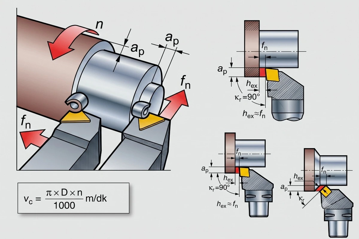

When G96 is active, the S value in the program is not RPM but a constant cutting speed in m/min; the control continuously recalculates the spindle speed based on the current diameter, so the speed rises as the tool moves to a smaller diameter. G97 is constant spindle speed (S directly in RPM). G50 is the upper spindle-speed limit that must not be exceeded during G96; if the calculated speed is below this limit it does not intervene, and it only caps the speed when it would be exceeded. The tool also suggests a suitable G50 value for the G96 program by computing the theoretical speed at the smallest machining diameter and adding a small margin.
Speed and feed in CNC milling (Vc, fz, ap, ae)
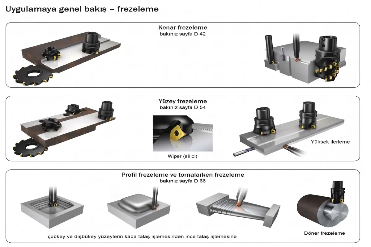
In milling the spindle speed is again found with n = 1000 × Vc / (π × Dc), where Dc is the cutter diameter. The table feed (Vf) is calculated from the feed per tooth fz, the effective number of teeth zc and the spindle speed n with Vf = fz × zc × n. ap is the axial depth of cut and ae the radial width of cut; maximum ae is especially critical for vibration in corner milling and plunging. Tool types such as a solid carbide end mill, an indexable mill, a face mill or a ball nose mill use the same formula; however, the applicable fz, ap and ae values change with the tool type and rigidity. In face milling the whole number of teeth may not be in cut at the same time, so the effective number of teeth (zc) can be entered separately for a more accurate table feed.
Speed and feed in CNC drilling (Vc, fn, Vf)
In drilling, efficiency largely depends on the feed rate (Vf). The spindle speed is again n = 1000 × Vc / (π × Dc), and the feed per minute is Vf = fn × n; fn is millimeters per revolution. Indexable-insert (U) drills give high efficiency at low cost in medium and large diameters; solid carbide drills offer tighter tolerances and better hole quality, and their feed per revolution is also higher. When the hole depth exceeds three times the diameter (3×Dc), internal coolant should be preferred for chip evacuation; dry drilling is not recommended in ISO M (stainless) and ISO S (titanium/HRSA) materials. Because cutting speed and feed also affect the cutting power (Pc) and torque (Mc), the feed should be kept low on thin or weakly clamped parts.

CNC speed and feed calculator
With the tool below you can enter, step by step, the operation type, material, tool and cutting values and calculate the spindle speed, feed, metal removal rate and time. The result shows the safe, normal and efficient mode separately.
Automatic values and source approach
When Vc, fn, fz, ap or ae are left blank, the tool assigns an automatic value based on the selected ISO material group and tool type, referencing the starting values and range midpoints in Sandvik Coromant technical catalogs; these are then corrected by the rigidity and surface-condition factors. When the user enters a value, the automatic value is bypassed and the entered value is used. The "Source status" section on the result screen shows whether each value is a user input or a catalog starting value. Mentor CNC is not affiliated with Sandvik Coromant and this tool is not an official product; for the most accurate result, enter the Vc, fz and fn values from your tool box or the manufacturer catalog.
⚠️ Warning: The automatic values are general starting values. Machine power, chuck limit, part balance, overhang, surface scale, slag, runout, interrupted cutting, tool geometry, coating and coolant can change them. Make the first trial in safe mode, in single block and with a low rapid approach; on the lathe, always check the G50 upper speed limit and the chuck manufacturer's limit.
In which order should you increase cutting data? (ap → fn → Vc)
Calculating speed and feed is not enough on its own. The order in which you increase the three variables decides both tool life and cost per part. Cutting tool manufacturers state this order clearly in their technical handbooks:
- Increase depth of cut (ap) first. ap has the smallest effect on tool life. Cutting 4 mm deep instead of 2 mm halves the number of passes without halving tool life.
- Then increase feed (fn / fz). The limit on feed is usually not tool life but surface finish, chip control and the fracture strength of the insert edge.
- Increase cutting speed (Vc) last. Vc has the largest effect on tool life; wear rises exponentially with cutting temperature.
The order is also economically correct. A 20% increase in cutting data can reduce cost per part by more than 10%, while a 50% improvement in tool life or a 30% reduction in tool cost typically lowers cost per part by only about 1% — because cutting tools account for an average of just 3–5% of total production cost. Investing in the variable that saves time pays far better than investing in the tool itself.
The Safe – Normal – Productive modes in the calculator above follow exactly this logic: run the first trial in Safe mode, and if chip form and surface are acceptable raise ap first, then feed, and only then step Vc up in small increments.
Are ap, fn and Vc too low or too high? Symptom table
At the machine, the chip form and the wear pattern on the insert tell you which value to pull back:
| Variable | If set too low | If set too high |
|---|---|---|
| Depth of cut ap | Chip control is lost, long stringy chips; the insert rubs instead of cutting; vibration and dimensional deviation; more passes and longer cycle time | Cutting force and power demand rise; deflection on slender or long parts; risk of insert fracture; machine torque may be insufficient |
| Feed fn / fz | Chip becomes too thin, friction instead of cutting; edge rounding and heat build-up; built-up edge; poor productivity | Surface roughness deteriorates rapidly; chip temperature and cutting force rise; crater wear and plastic deformation; chip jamming |
| Cutting speed Vc | Built-up edge (BUE) formation — especially in low carbon steel, stainless and aluminium; surface degrades; low productivity | Rapid wear, crater wear and plastic deformation; edge depression; tool life falls off exponentially |
Corner radius (rε), the feed limit and surface finish
The most frequently skipped part of any speed and feed calculation is that the upper limit of feed is set by the corner radius of the insert. A larger radius spreads the contact over a longer arc and tolerates a higher feed:
| Corner radius rε (mm) | Recommended maximum feed fn (mm/rev) |
|---|---|
| 0.4 | 0.25 – 0.35 |
| 0.8 | 0.40 – 0.70 |
| 1.2 | 0.50 – 1.00 |
| 1.6 | 0.70 – 1.30 |
| 2.4 | 1.00 – 1.80 |
Depth of cut versus corner radius: ap should not be smaller than 2/3 of the corner radius (ap ≥ 2/3 × rε). Below that, cutting takes place only on the radius, the cutting force shifts into the radial direction, and the result is vibration, loss of chip control and dimensional deviation. Example: with rε 1.2 mm, ap should be at least 0.8 mm.
Theoretical surface roughness: the best finish you can reach in turning can be calculated in advance from feed and corner radius:
Rmax = fn² × 125 / rε (µm; fn in mm/rev, rε in mm)
The squared term is the key: doubling the feed makes roughness four times worse. With fn 0.20 mm/rev and rε 0.8 mm, Rmax ≈ 6.3 µm; with the same insert at fn 0.40 mm/rev, Rmax ≈ 25 µm. The calculator above shows this value for your selected feed at four different corner radii in the results panel.
Wiper inserts: wiper geometries add a small flat section behind the corner radius that smooths out the feed marks. They are used in two ways: about twice the surface quality at the same feed, or about twice the feed at the same surface quality. Negative -WMX geometries are the first choice in roughing to medium machining, positive -WF in finishing. In parting and grooving a wiper radius improves the surface but does not allow the feed to be doubled.
How far can you safely raise Vc? Coolant, entering angle and rigidity
- High pressure coolant (HP): the benefit starts at roughly 10 bar and becomes marked up to 70 bar. Because it breaks the chip away from the cutting edge it improves chip control and tool life, and in ISO M (stainless) and ISO S (titanium, superalloys) it allows an increase of 30–50% in Vc.
- Entering angle (KAPR): an angle close to 90° directs the cutting force axially and reduces vibration on slender parts. A small entering angle (45°–75°) thins the chip, allows higher feed and reduces notch wear, but increases radial force and vibration. For the same depth of cut a smaller angle needs a longer cutting edge: at ap 5.0 mm, KAPR 75° needs about a 5.2 mm edge while KAPR 45° needs 7.1 mm.
- Boring bar overhang: ≤ 3×D with a steel bar; 3–6×D requires a damped or carbide bar; 5–7×D requires a carbide reinforced damped bar. Deflection grows with the cube of the overhang, so the first values to reduce are ap and feed, not Vc.
- In parting off: reduce the feed by 75% about 2 mm before the centre and stop the feed 0.5 mm before the centre. Otherwise cutting speed falls to zero at the centre while the feed stays the same, and the insert breaks.
Metal removal rate (Q), machining time (Tc), power and torque
Speed and feed alone are not a measure of productivity. Two operations can run at the same spindle speed and remove very different amounts of material. The real measure is the metal removal rate Q (cm³/min) — the volume of material removed per unit of time:
| Operation | Metal removal rate Q (cm³/min) |
|---|---|
| Turning | Q = Vc × ap × fn |
| Milling | Q = ap × ae × Vf / 1000 |
| Drilling | Q = Dc × fn × Vc / 4 |
If you fill in ap (and ae for milling) in the tool above, Q is calculated automatically in the results panel. When comparing two cutting strategies, compare Q — not spindle speed.
Machining time: if lm is the length travelled in one pass, Tc = lm / (fn × n) for turning and drilling, or Tc = lm / Vf for milling. Enter lm in the calculator and the time is shown in minutes and seconds. For a full cycle calculation including setup, tool change and rapid moves, use the CNC machining cycle time and cost per part calculator.
Net power and torque: to check whether your chosen values exceed the machine capacity:
| Quantity | Formula |
|---|---|
| Net power Pc (kW) — turning | Pc = Vc × ap × fn × kc / (60 × 10³) |
| Net power Pc (kW) — milling | Pc = ap × ae × Vf × kc / (60 × 10⁶) |
| Torque Mc (Nm) | Mc = Pc × 30 × 10³ / (π × n) |
| Specific cutting force kc (N/mm²) | kc = kc1 × hm–mc × (1 – γ₀/100) |
kc is the specific cutting force of the material and varies with the average chip thickness hm (in turning, hm = fn × sin κr). For a calculation compared against your machine’s speed–torque curve, see the CNC spindle torque calculator. In large diameter roughing at low spindle speed the limit is usually torque, not power.