
How a chip forms and why it breaks in CNC turning is just as important as choosing the right spindle speed. The Mentor CNC guide below explains chip formation, chip-breaking mechanisms, and the relationship between feed (fₙ), depth of cut (aₚ), corner radius, insert geometry and tool approach angle (KAPR); it then calculates the theoretical maximum uncut chip thickness — the hex value — from your tool and parameters. The tool can automatically read KAPR from a holder code such as PDJNR or TCLNR, and the corner radius from an insert code such as DNMG 150608.
MENTOR CNC TECHNICAL GUIDE AND CALCULATOR
Chip Formation, Metal Removal, Chip Breaking and Maximum Chip Thickness hex Calculation in CNC Turning
Safe and stable production in turning is not only about choosing the right spindle speed. The insert geometry, the tool approach angle, the corner radius, the depth of cut, the feed per revolution, the cutting speed, the workpiece material, the coolant and the system rigidity all work together to determine how the chip will form. This Mentor CNC page explains in detail why a chip becomes long or breaks, and calculates the theoretical maximum uncut chip thickness — the hex value — from the parameters you use.
Are metal removal, chip formation and chip breaking the same thing in turning?
On the shop floor, expressions such as “shaving”, “taking material” or “metal removal” are used frequently. Technically, the insert entering the workpiece and removing the metal layer between the uncut surface and the machined surface is the metal removal operation. This metal layer is subjected to pressure and cutting stress in front of the insert, deforms plastically, passes through the shear zone and flows out along the rake face of the insert. This stage is called chip formation.
Whether the resulting chip continues as an uninterrupted ribbon or separates into short, controlled pieces is not the same thing. Separating the chip into safe lengths is called chip breaking. Therefore, the cutting tool may be removing metal, but chip control may not be good. Especially in steel, stainless steel, aluminum, titanium and nickel-based materials, long and wrapping chips can form even though cutting is taking place.
Metal removal
The insert removing a metal layer from the workpiece with defined ap and fn values.
Chip formation
The compression, deformation, flow along the rake face and curling of the uncut layer.
Chip breaking
The controlled-length separation of the formed chip and its safe evacuation from the cutting zone.
Why is the chip thickness measured with a caliper not hex?
During cutting, the metal is compressed, deforms in the shear plane, heats up and curls. For this reason the thickness of the chip leaving the machine, measured with a caliper, is not the same as the thickness of the metal layer before it was cut. The removed chip is usually thicker than the theoretical uncut chip. hex is not the physical size of the removed chip; it is the theoretical maximum thickness of the uncut layer that the cutting edge encounters.
How is a chip broken in turning?
Chip control is one of the main success criteria in turning. In good chip control, the goal is not always to produce the smallest possible dust-like piece. The goal is to produce short or medium-length controlled chips that do not wrap around the chuck, tool and part, do not scratch the machined surface, do not stop automatic operation, and are evacuated without creating a hazard for the operator.
1. Self-breaking of the chip
In brittle materials the chip can separate naturally due to its own structure and curling stress. Cast iron is a typical example. However, very short and hard chips can fly off at high speed; therefore the “the shorter the better” approach is not correct.
2. Breaking by hitting the rake face of the insert
The chip breaker groove forces the outgoing chip into a small curl radius. When the chip presses against the insert geometry and the bending stress rises, it snaps. This is one of the basic working principles of modern finishing, medium and roughing chip geometries.
3. Breaking by hitting the workpiece
The chip can curl and break by hitting the workpiece. However, if the chip continuously strikes the machined surface, it can scratch the surface or become jammed between the tool and the part. Being broken alone does not mean the chip is well controlled.
How does the chip breaker groove work?
The grooves, bumps and guiding geometries on the rake face of the insert are generally called the “chip breaker”, or on the shop floor the “chip groove”. The chip breaker determines the flow direction of the chip, the curl radius, and how much the cutting edge is supported. A fine-chip geometry can be sharper and more closed to work at small ap and low fn values. A roughing geometry, on the other hand, needs a stronger edge and a more open groove to carry large chip sections.
Chip breaker geometries are generally classified into three application areas: F fine/finishing, M medium and R roughing. For example, designations such as PF–PM–PR in steels, MF–MM–MR in stainless steels, and KF–KM–KR in cast irons can be seen. These suffixes can be manufacturer-specific; they should not be interpreted as a universal ISO standard. The correct application area must be verified from the insert manufacturer's ap–fn application chart.
Key turning parameters that affect chip breaking
1. Feed per revolution fn
Values programmed on the lathe such as F0.20, F0.25 or F0.30 are mostly feed per revolution in mm/rev. As fn increases, the uncut chip thickness and the cutting edge load increase. At very low feed, the chip may not create enough pressure on the selected chip breaker groove; long, thin and tangled chips can form. If the feed is increased more than necessary, cutting edge breakage, poor surface, plastic deformation or part deflection can occur.
If you do not know your feed value, you can use the Mentor CNC CNC lathe speed and feed calculator. In this hex tool, instead of estimating the feed automatically, it is more accurate to enter the box or catalog value of the insert you are using.
2. Depth of cut ap
ap is the radial distance between the unmachined and machined surface. When going from Ø50 to Ø46 in a single pass, even though the diameter difference is 4 mm, the radial depth of cut is 2 mm. If ap stays too small, cutting can occur only at the tip of the corner radius; the chip breaker groove may not engage enough, the insert may rub the part instead of cutting it, and vibration can occur. As ap grows, the chip section and power requirement increase.
3. Cutting speed Vc and spindle speed
Vc can affect cutting temperature, built-up edge tendency, tool wear and the flow behavior of the chip; but on standard straight-edged inserts it is not part of the hex formula. In other words, when Vc changes the chip behavior may change, but if fn and the approach angle are constant, the theoretical hex stays the same. For speed, diameter and Vc calculation use the separate CNC lathe speed–feed page.
4. Tool approach angle KAPR / κr
The approach angle determines how the feed is distributed to the cutting edge. On tools around 90°–95°, hex is very close to the fn value. At smaller angles such as 45°, 50° or 75°, the same program feed turns into a thinner but wider chip. This “chip thinning” effect can spread the load over a longer part of the cutting edge. However, the direction of the radial and axial forces also changes; for thin and long parts, a decision should not be made by looking at the hex value alone.
| KAPR | sin(KAPR) | hex for F0.30 | Comment |
|---|---|---|---|
| 45° | 0.707 | 0.212 mm | Significant chip thinning |
| 75° | 0.966 | 0.290 mm | Slight chip thinning |
| 90° | 1.000 | 0.300 mm | hex = fn |
| 93° | 0.999 | 0.300 mm | Practically same as fn |
| 95° | 0.996 | 0.299 mm | Practically same as fn |
| 107.5° | 0.954 | 0.286 mm | Slight chip thinning |
5. Corner radius rε
The corner radius affects surface quality, chip breaking, insert strength and radial cutting force. A small radius can be useful at small depths of cut and on parts with vibration risk, but the cutting edge is weaker. A large radius can withstand higher feed and greater depth of cut, but it increases radial forces and can deflect a long, thin part.
As a general application check, keeping ap below approximately 2/3 × rε can increase the likelihood of problems, especially in chip control. This is not an absolute law; finishing geometry, wiper design and manufacturer charts take priority. If the tool can read the corner radius from the insert code, it checks this ratio automatically.
6. Positive and negative inserts
Inserts whose second letter is N, such as CNMG, DNMG, WNMG and SNMG, are negative basic-shape inserts with zero clearance angle that can be used double-sided. They offer a strong cutting edge and the advantage of multiple corners; however, cutting forces can be higher than positive inserts. Positive inserts with a clearance angle, such as CCMT, DCMT, TCMT and VCMT, cut more sharply and provide lower cutting force; they can be advantageous on thin-walled, small or long parts. Being positive or negative does not change the basic hex formula of straight-edged inserts, but it changes the applicable fn, ap and cutting force.
7. Part and tool rigidity
The same hex value does not give the same result on a short, rigid part and on a long, thin shaft. Tailstock support, overhang from the chuck, long steps dropping from Ø50 to Ø20, the L/D ratio of the boring bar, the tool holder section and machine clearances determine vibration. hex shows the theoretical thickness that the cutting edge encounters; it does not show how much the part will deflect under this load.
8. Cutting fluid and high-pressure coolant
Directing the cutting fluid to the correct point can improve chip flow, temperature and evacuation. Especially in stainless steel, titanium and nickel-based alloys that form long chips, internal or high-pressure coolant can help chip control. Nevertheless, it is not always possible to fix a chip breaker working in the wrong fn–ap zone with coolant alone.
Insert shapes and tool codes used in turning
In the calculator, the insert shape is used to identify the user's tool and to show the correct application interpretation. On standard straight-edged C, D, S, T, V and W inserts, the hex calculation is mainly determined by fn and the KAPR value. On R-type round inserts, because there is no fixed approach angle, a separate formula is used.
Why is the tool code more important than the insert code?
DNMG or DCMT describes the shape and clearance structure of the insert; but the angle at which the tool approaches the workpiece is mainly determined by the holder code. For example, different holders can use the same D-shaped insert at 93° or 107.5° KAPR. Therefore the tool, if possible, reads the holder code such as PDJNR, TDJNR, TCLNR, SCLCR, SDJCR and finds the KAPR value automatically. If the code is not recognized, the user can select the angle manually.
How is the corner radius read from the insert code?
In many ISO insert codes, the last two digits are the corner radius code. For example, the 08 at the end of DNMG 150608 or DCMT 11T308 usually indicates a 0.8 mm corner radius. 04 means approximately 0.4 mm, 12 approximately 1.2 mm and 16 approximately 1.6 mm. Because the diameter coding of round inserts can be different, the insert diameter is asked separately when R type is selected.
What is the maximum chip thickness hex and what does it tell the operator?
hex is the thickest part of the uncut chip that the cutting edge encounters during one revolution. It shows the actual geometric effect of the programmed feed on the cutting edge. If F0.30 is used on a 93° tool, hex is approximately 0.30 mm. On a 45° tool, the same F0.30 produces approximately 0.212 mm hex. For this reason, on tools with different KAPR values, the same F code does not create the same cutting edge load.
Straight-edged C, D, S, T, V and W inserts
hex = fn × sin(KAPR)
fn: feed in mm/rev · KAPR: tool approach angle
Round R-type inserts
hex = fn × √[(4ap/iC) − (2ap/iC)²]
ap: radial depth of cut · iC: round insert diameter
hex does not give you the spindle speed or Vc directly. Its job is to show the theoretical chip thickness that the feed and tool geometry you selected create at the cutting edge. Since chip breaker application charts are usually given over ap and fn, hex is a complementary engineering value for comparing different tool angles and understanding the cutting load.
MENTOR CNC CALCULATOR
CNC Lathe hex and Chip Control Calculator
For a quick calculation, the tool code or KAPR, the feed and the depth of cut are enough. Material, machining type, insert code and rigidity information improve the interpretation of the result; they do not change the basic formula.
Chip control assessment for the operator
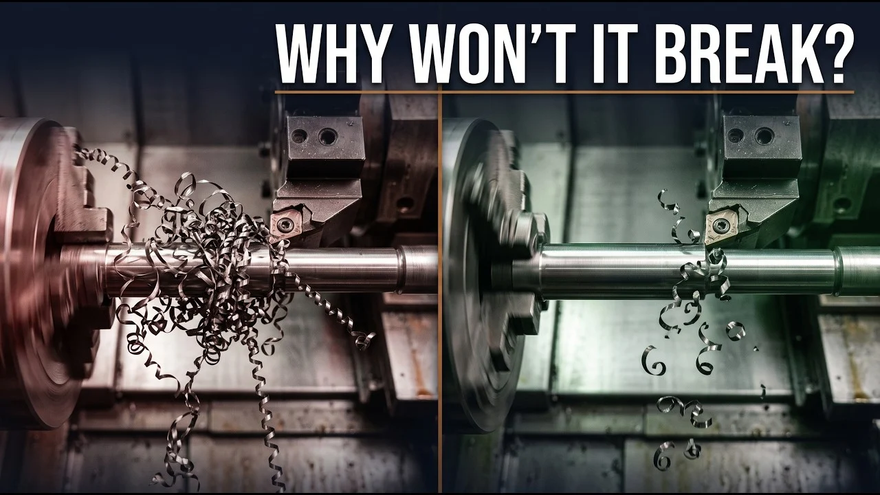
Video: chip breaking and hex in turning
When you press play, the video is loaded from YouTube (Google) servers. Watch on YouTube ↗
This 11-minute lesson separates metal removal, chip formation and chip breaking, explains why a chip measured with a caliper is not hex, and shows the working range of F/M/R chip breakers. A KAPR simulation demonstrates hex = fn × sin(KAPR), then the calculator above is used for four worked examples: PDJNR + DNMG, a 45° tool, a finishing pass and a round insert. The chapter links start the video at the matching step.
- 0:48 – Metal removal, chip formation and chip breaking
- 1:21 – Why a caliper-measured chip is not h_ex
- 1:48 – F / M / R chip breakers
- 2:27 – Parameters that affect chip breaking
- 3:18 – KAPR simulation: h_ex = fn × sin(KAPR)
- 4:42 – h_ex on round R-type inserts
- 5:38 – Tool holder and insert codes (PDJNR, DNMG)
- 6:15 – The calculator: input fields
- 6:43 – Example 1 – PDJNR + DNMG, F0.30
- 8:18 – Example 2 – Chip thinning with a 45° tool
- 8:58 – Example 3 – Finishing pass and ap/rε warning
- 9:38 – Example 4 – Round insert
- 10:34 – Chip behavior by material and troubleshooting
How does chip behavior change by material?
ISO P — Steels
In unalloyed, carbon and low-alloy steels, chip control can usually be achieved with suitable fn, ap and F/M/R geometry. Although medium-carbon engineering steels such as 1040 are generally machinable, low feed or an unsuitable chip breaker can cause long spiral chips. Common geometry families for steel are PF, PM and PR.
ISO M — Stainless steels
Stainless steels can form long, tough and sticky chips. Very low feed can increase friction and work hardening instead of cutting. Sharp geometry, stable cutting, correct Vc and effective coolant are important. Common geometry families are MF, MM and MR.
ISO K — Cast irons
Gray cast iron chips are mostly short and brittle; natural breaking is easier. Nevertheless, the abrasive structure can affect tool life. Geometries such as KF, KM and KR can be used for cast iron.
ISO N — Aluminum and non-ferrous materials
Some aluminum alloys are long-chipping; pure and soft aluminum can stick to the cutting edge. A polished, sharp positive geometry and a wide chip space are important. AL-type geometries are common in this group.
ISO S — Titanium and heat-resistant alloys
Titanium and nickel-based alloys can create high temperature and cutting edge load in the cutting zone. Chip control is difficult; the cutting fluid reaching the correct point and stable parameters become important. Geometries such as SM and SR can be seen.
ISO H — Hardened steels
The chip can often be shorter; but the insert grade, edge preparation, surface requirement and impact cutting risk become critical. Geometry families such as HM and HR can be used.
If the chip does not break in turning, in what order should you check?
- Feed fn: Is it too low for the chip breaker? Does a small increase change the chip shape?
- Depth of cut ap: Is cutting staying only at the tip of the corner radius?
- Chip breaker code: Is a roughing pass being done with finishing geometry, or a very fine pass with roughing geometry?
- Tool KAPR angle: Is the same F value producing a thinner hex than expected due to a smaller KAPR?
- Corner radius: Is rε compatible with ap and fn?
- Cutting speed Vc: Is there built-up edge, excessive heat or unstable chip flow?
- Coolant: Is it directed toward the chip flow and at sufficient pressure?
- Rigidity: Are the part, tailstock, tool overhang, boring bar and machine clearances suitable?
If long, wrapping chips are seen
First look at the insert manufacturer's ap–fn working area. If the parameters are below the working area, the feed or depth of cut can be increased in a controlled way. A more closed finishing/medium chip breaker, a smaller corner radius or more effective coolant can be considered. If the part is thin, the effect of the feed increase on deflection and vibration must definitely be checked.
If very short, hard, flying chips are seen
The feed and ap may be higher than necessary, the chip breaker too closed, or the material naturally brittle. If the cutting edge is taking impact load, the feed, geometry and Vc should be evaluated together. The machine guard should be kept closed; the chip should not be touched by hand.
If there is vibration and dimensional deviation
Even if hex looks appropriate, a large corner radius, high radial force, long part overhang or a long tool can create vibration. A smaller radius, positive geometry, short tool overhang, more solid clamping, a tailstock or a suitable anti-vibration tool may be needed. If the problem is addressed only by reducing the feed, chip breaking can get even worse.
Common mistakes CNC operators make in chip thickness and chip breaking
- Measuring the curled chip with a caliper and thinking it is hex.
- Adding the part diameter or spindle speed directly into the hex formula.
- Thinking that the DNMG, DCMT or CNMG code alone gives the tool approach angle.
- Assuming the same F value creates the same cutting edge load on a 93° and a 45° tool.
- Always considering very low feed as safe; overlooking friction and poor chip breaking.
- Entering the ap value as the diameter difference; calculating the radial depth of cut as double.
- Confusing corner radius with the Ra surface roughness value.
- Accepting chip breaker suffixes as meaning the same thing across all manufacturers.
- Evaluating insert capacity on a long shaft or boring bar independently of part/tool rigidity.
Evaluate together for correct chip control in CNC turning
The best result is obtained by evaluating the insert geometry, KAPR, corner radius, fn, ap, Vc, material and rigidity together. The hex calculation is an important but, on its own, insufficient part of this system.
Open the Vc, Speed and Feed Calculator