
Notes from the Shop Floor: What We Learned Tapping Parts
This section is not theory. These are lessons from years of tapping — some paid for with broken taps and scrapped parts.
Use a tapping attachment on the machining center
When tapping on machining centers we use a tapping attachment (tension-compression holder). Its built-in axial float and mechanical give absorb small pitch/feed mismatches in synchronized tapping, let the tap ease into the hole, and lower the risk of breakage. Even on rigid synchronized-tapping machines, the attachment gives us a safety margin on small-diameter, precision work.
How a tap breaks: high speed shatters like glass, low speed seizes
We saw a clear pattern in the shop: run the tap at the correct, adequate speed/feed (Vc) and even if it breaks it shatters like glass and does not seize in the hole — the part is easy to save. Run the same tap too slow and it breaks like a heavy bar and jams in the hole. A tap broken at high speed usually does not seize; a tap broken at low speed seizes as it breaks. So dropping the speed "to be safe" often makes the job harder, not easier.
Removing a broken tap
We save a broken tap when we can. Pieces that have not seized come out mechanically. For seized ones we weld onto the tap stub — the heat anneals and softens the tap steel and gives us a grip — and back it out by turning; sometimes we weld into the same spot and re-machine. If the part allows it and the customer grants a deviation, we recover the part this way.
When to tap, when to single-point thread?
For work too small for any threading tool (a lathe threading insert or a thread mill) to enter, we tap: M5, M6, M8. M10–M12 and up depend on the part and the tolerance. The real question is the thread tolerance the customer specifies on the drawing: how tight, which tolerance class will they accept? That decides tap vs. cutting vs. form tap.
Tapping Techniques and Tap Drill Size Calculator
This page brings together the practical shop-floor decisions around tap selection in one place. Which tap is more suitable in a blind hole, which way should chips go in a through hole, what each chamfer type does, which drill diameter to use for metric or UNC/UNF/Whitworth threads and how to calculate speed–feed in tapping — you will find clear, practice-oriented answers to these core questions.
Important note: This content is an independent technical summary prepared for Mentor CNC. It does not recommend a specific brand, product code or special series. The advice here is simplified based on the common approach of major cutting-tool manufacturers, standard thread geometries and general machining principles.
What's on this page?
Tapping is often seen as only a "diameter minus pitch" calculation. Yet the real problems on the floor are usually caused by the wrong tap type, the wrong chamfer type, the actual hole coming out different, insufficient bottom clearance in blind holes, poor lubrication or the wrong cutting speed for the material. If you follow the flow below, you will get far more useful results from the calculator at the end of the page.
Why should a CNC operator read this page?
Why do taps break?
The most common causes are a tight actual hole, the wrong tap type, chip packing in blind holes, insufficient cutting fluid, wrong speed and a feed that is not synchronized. You can check the tolerance band of the pilot hole with the hole tolerance calculator.
Why does the thread go in hard?
If the pilot hole is too small, thread engagement rises needlessly and torque increases. If the pilot hole is too large, the thread becomes loose. So consider not only the drill diameter but, if possible, the actual hole diameter.
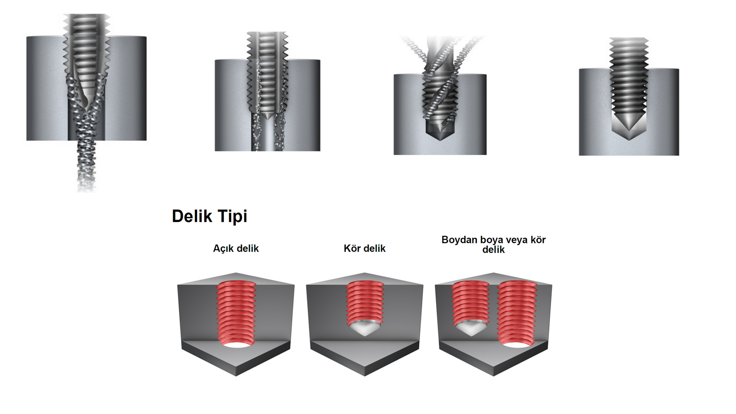
Which tap for which hole?
A spiral point tap is generally used in through holes, a spiral flute tap in blind holes, a straight flute tap in short-chipping materials and a roll (form) tap in ductile materials.
Tap types and when to use them
The drawings below are reference, original and simplified schematics. They are not actual product drawings but educational visuals explaining the usage logic.
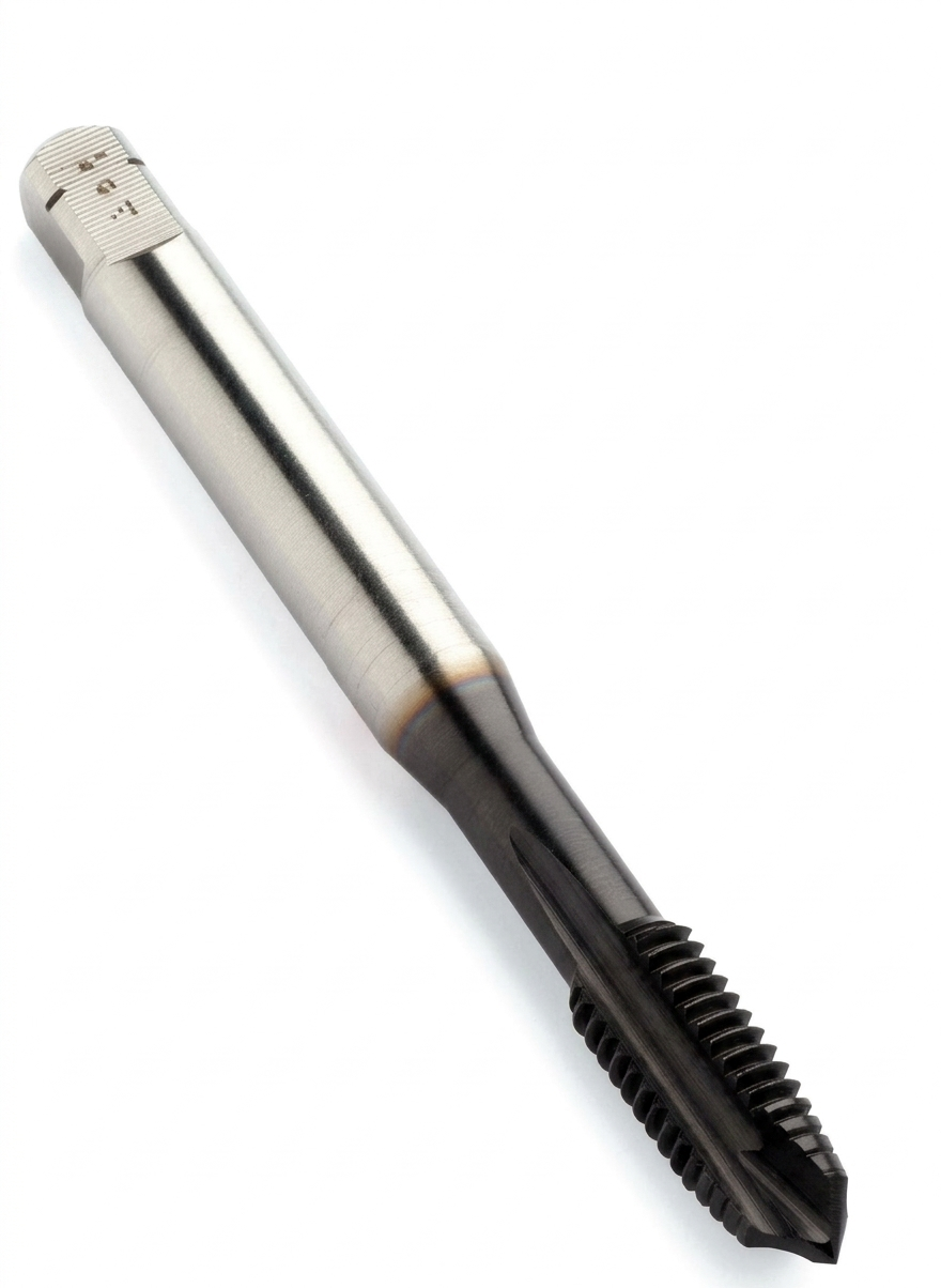
Spiral point taps
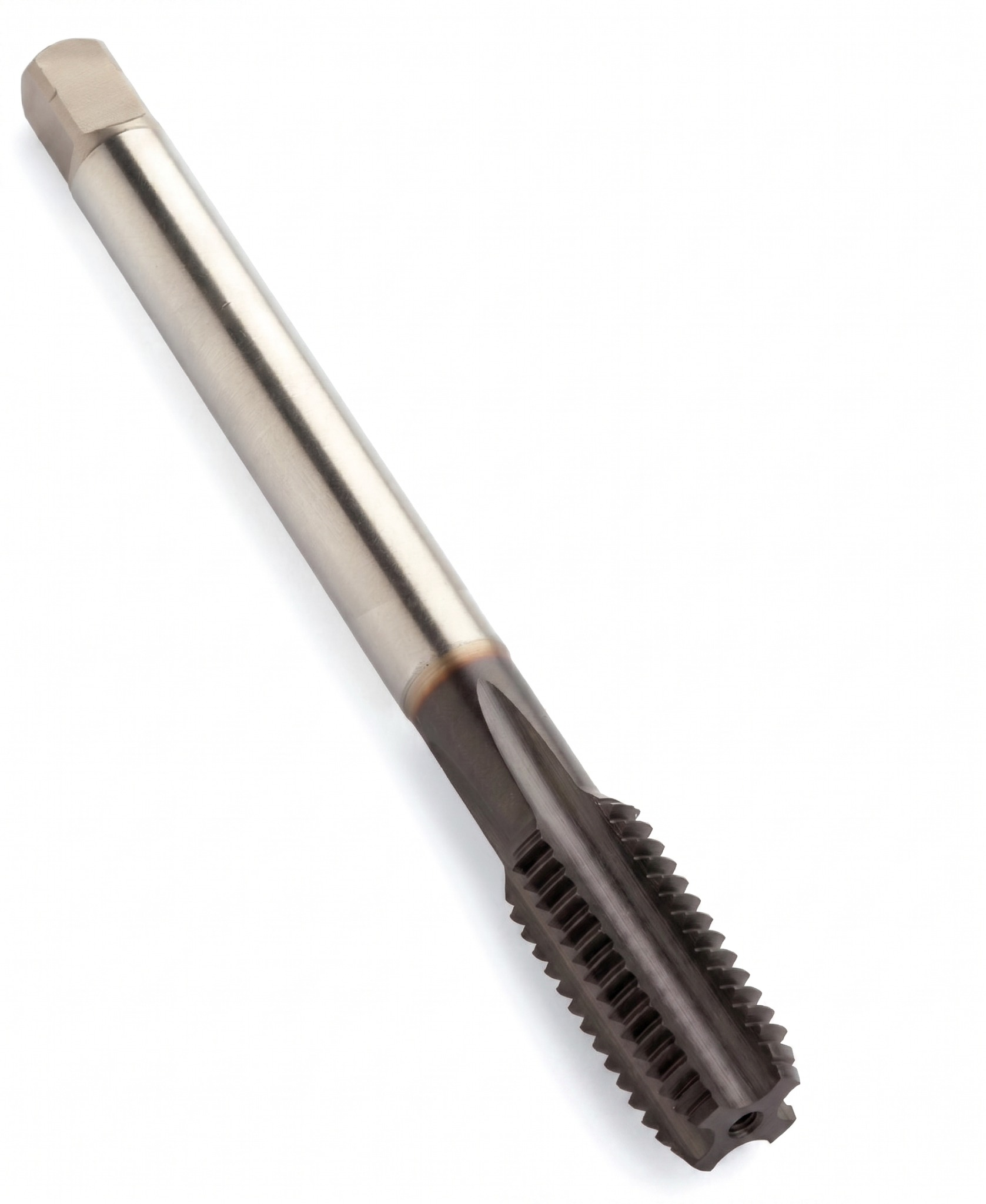
One of the most common choices for through holes. It tends to push chips forward, toward the exit side of the hole. It works well especially in materials that form continuous chips.
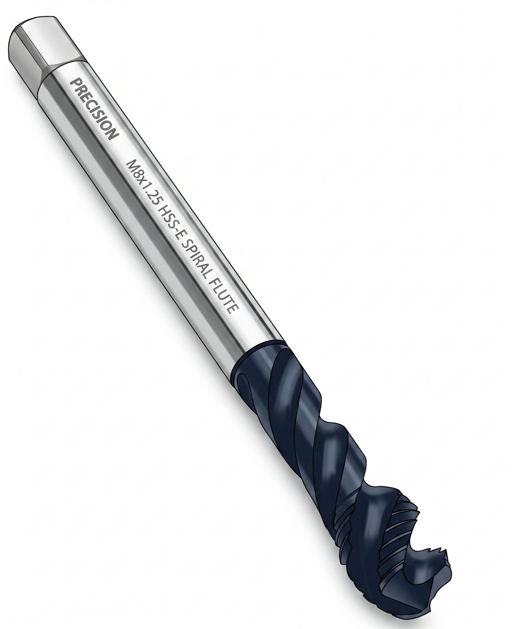
Spiral flute taps
One of the safest options for blind holes. It pulls chips upward, reducing build-up at the bottom of the hole. Often preferred in stainless and hard-to-control-chip materials.
Straight flute cutting taps
Can be used in short-chipping materials, general-purpose applications or hand tapping. It does not aggressively direct chips forward or backward; so chip behavior must be watched.
Roll (form) taps
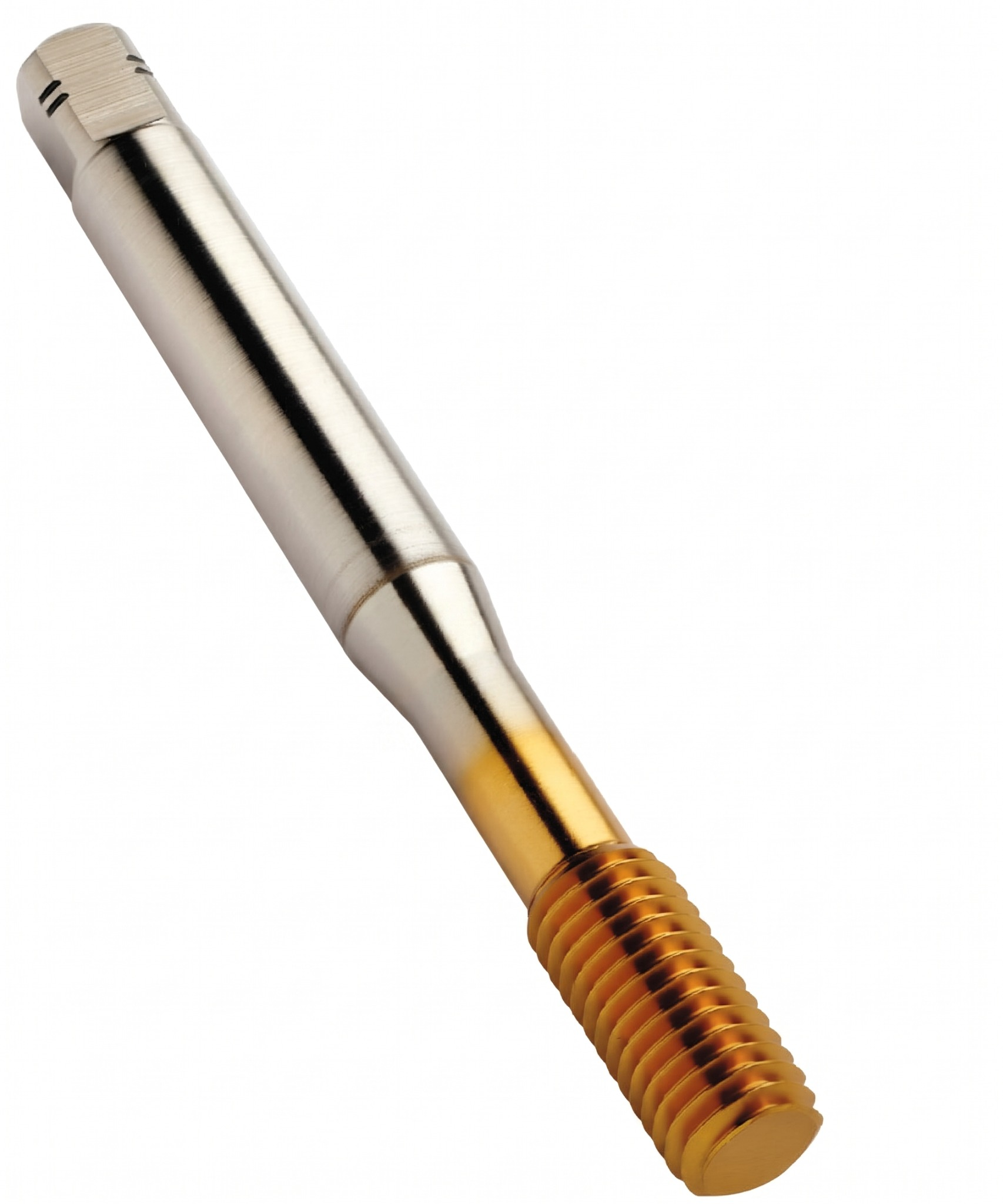
It does not cut and produces no chips; it shapes the material by plastic deformation. For this reason it offers an advantage in ductile materials and under good lubrication. The hole diameter is chosen larger than for a cutting tap.
| Tap type | Best hole type | Main advantage | Watch out for |
|---|---|---|---|
| Spiral point | Through hole | Pushes chips toward the exit | May pack chips at the bottom of a blind hole |
| Spiral flute | Blind hole | Carries chips upward | Can also be used in through holes but may not always be the first choice |
| Straight flute | Short-chipping material, general purpose | Simple and widely used | Chip control may weaken in continuously chipping material |
| Roll (form) | Blind or through, ductile material | Produces no chips, can improve surface and strength | Needs a larger pilot hole and good lubrication; not suitable for brittle materials |
Tap chamfer (lead) types
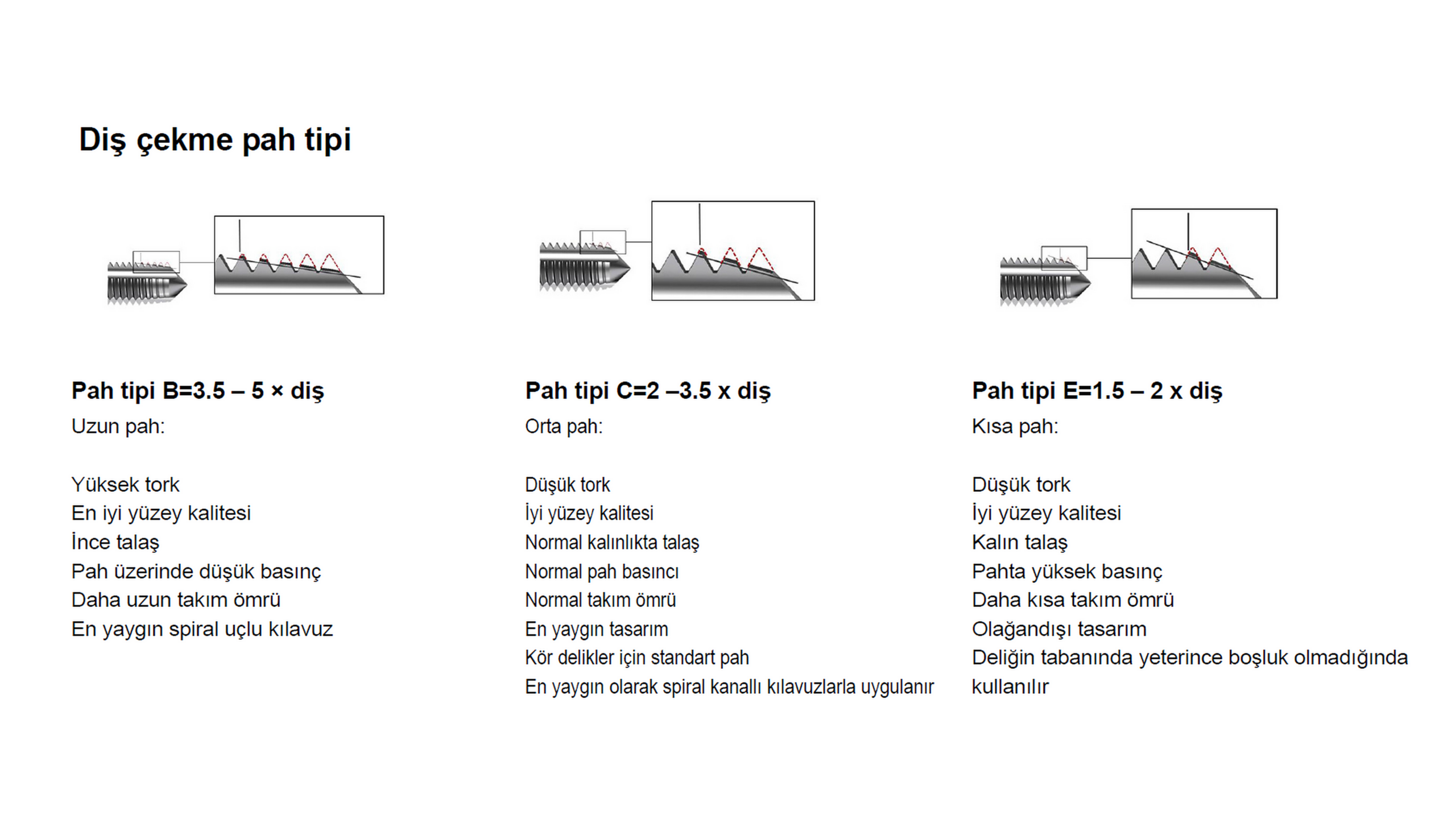
The chamfer length of the tap engages the teeth gradually so that cutting does not start at full load all at once. The B, C and E types below have a direct effect on blind holes, through holes, torque and tool life.
Chamfer type B = 3.5 – 5 threads
- Considered a long chamfer.
- Makes torque distribution smoother.
- Can provide good surface quality and low chamfer pressure.
- Generally advantageous in through holes and continuous production.
Chamfer type C = 2 – 3.5 threads
- A medium chamfer structure.
- Provides normal torque, normal chamfer pressure and balanced tool life.
- One of the most common standard solutions for blind holes.
- Frequently seen on spiral flute taps.
Chamfer type E = 1.5 – 2 threads
- A short chamfer type.
- Useful when clearance at the bottom of the hole is limited.
- Unit load on the chamfer increases; tool life may be shorter.
- Can be considered to get the maximum possible full-thread length in a blind hole.
Recommended tap-drill sizes
Before cutting an internal thread, the most critical step is choosing the correct pilot-hole diameter. The value to choose depends on the thread standard, the pitch, the tap type and the material. The tables below are practical references prepared for quick decisions on the shop floor.
General logic for cutting taps
- In the metric and UN series the quick shop rule is usually drill diameter ≈ nominal diameter − pitch.
- This approach gives a sufficient starting point in most standard applications.
- In high-strength or tough material, a slightly larger pilot hole can be chosen if needed to reduce torque.
General logic for form taps
- Since no chips are produced with a form tap, the pilot hole is chosen larger than for a cutting tap.
- If the cutting-tap hole diameter is used by mistake, torque rises sharply.
- Good lubrication and a ductile material are critically important with a form tap.
The hole sizes in the table are standard shop advice. Special tolerances, a low-torque target or a form tap may require different values.
Complete tap-drill size tables by standard (cutting taps)
The tables below give the pre-machined hole diameter (PHD) for cutting (chip-forming) taps and the maximum hole diameter (PHDX) for the relevant tolerance class. PHD is a nominal recommendation; measure the actual hole on precision work.
| TDZ | Pitch (mm) | PHD (mm) | PHDX (mm) | PHD (inch) | PHDX (inch) |
|---|---|---|---|---|---|
| M1 | 0,25 | 0,75 | 0,785 | 0,0295 | 0,0309 |
| M1,1 | 0,25 | 0,85 | 0,885 | 0,0335 | 0,0348 |
| M1,2 | 0,25 | 0,95 | 0,985 | 0,0374 | 0,0388 |
| M1,4 | 0,30 | 1,10 | 1,142 | 0,0433 | 0,0450 |
| M1,6 | 0,35 | 1,25 | 1,321 | 0,0492 | 0,0520 |
| M1,8 | 0,35 | 1,45 | 1,521 | 0,0571 | 0,0599 |
| M2 | 0,40 | 1,60 | 1,679 | 0,0630 | 0,0661 |
| M2,2 | 0,45 | 1,75 | 1,838 | 0,0689 | 0,0724 |
| M2,5 | 0,45 | 2,05 | 2,138 | 0,0807 | 0,0842 |
| M3 | 0,50 | 2,50 | 2,599 | 0,0984 | 0,1023 |
| M3,5 | 0,60 | 2,90 | 3,010 | 0,1142 | 0,1185 |
| M4 | 0,70 | 3,30 | 3,422 | 0,1299 | 0,1347 |
| M5 | 0,80 | 4,20 | 4,334 | 0,1654 | 0,1706 |
| M6 | 1,00 | 5,00 | 5,153 | 0,1969 | 0,2029 |
| M7 | 1,00 | 6,00 | 6,153 | 0,2362 | 0,2422 |
| M8 | 1,25 | 6,80 | 6,912 | 0,2677 | 0,2721 |
| M9 | 1,25 | 7,80 | 7,912 | 0,3071 | 0,3115 |
| M10 | 1,50 | 8,50 | 8,676 | 0,3346 | 0,3416 |
| M11 | 1,50 | 9,50 | 9,676 | 0,3740 | 0,3809 |
| M12 | 1,75 | 10,20 | 10,441 | 0,4016 | 0,4111 |
| M14 | 2,00 | 12,00 | 12,210 | 0,4724 | 0,4807 |
| M16 | 2,00 | 14,00 | 14,210 | 0,5512 | 0,5594 |
| M18 | 2,50 | 15,50 | 15,744 | 0,6102 | 0,6198 |
| M20 | 2,50 | 17,50 | 17,744 | 0,6890 | 0,6986 |
| M22 | 2,50 | 19,50 | 19,744 | 0,7677 | 0,7773 |
| M24 | 3,00 | 21,00 | 21,252 | 0,8268 | 0,8367 |
| M27 | 3,00 | 24,00 | 24,252 | 0,9449 | 0,9548 |
| M30 | 3,50 | 26,50 | 26,771 | 1,0433 | 1,0540 |
| M33 | 3,50 | 29,50 | 29,771 | 1,1614 | 1,1721 |
| M36 | 4,00 | 32,00 | 32,270 | 1,2598 | 1,2705 |
| M39 | 4,00 | 35,00 | 35,270 | 1,3780 | 1,3886 |
| M42 | 4,50 | 37,50 | 37,799 | 1,4764 | 1,4881 |
| M48 | 5,00 | 43,00 | 43,297 | 1,6929 | 1,7046 |
| M52 | 5,00 | 47,00 | 47,297 | 1,8504 | 1,8621 |
| M56 | 5,50 | 50,50 | 50,796 | 1,9882 | 1,9998 |
| M64 | 6,00 | 58,00 | 58,305 | 2,2835 | 2,2955 |
| TDZ | Pitch (mm) | PHD (mm) | PHDX 6H (mm) |
|---|---|---|---|
| M2,5 | 0,35 | 2,15 | 2,221 |
| M3 | 0,35 | 2,65 | 2,721 |
| M3,5 | 0,35 | 3,15 | 3,221 |
| M4 | 0,50 | 3,50 | 3,599 |
| M5 | 0,50 | 4,50 | 4,599 |
| M6 | 0,75 | 5,25 | 5,378 |
| M7 | 0,75 | 6,25 | 6,378 |
| M8 | 1,00 | 7,00 | 7,153 |
| M8 | 0,75 | 7,25 | 7,378 |
| M10 | 1,00 | 9,00 | 9,153 |
| M10 | 1,25 | 8,80 | 8,912 |
| M12 | 1,00 | 11,00 | 11,153 |
| M12 | 1,25 | 10,75 | 10,912 |
| M12 | 1,50 | 10,50 | 10,676 |
| M14 | 1,50 | 12,50 | 12,676 |
| M16 | 1,50 | 14,50 | 14,676 |
| M18 | 1,50 | 16,50 | 16,676 |
| M20 | 1,50 | 18,50 | 18,676 |
| M20 | 2,00 | 18,00 | 18,210 |
| M22 | 1,50 | 20,50 | 20,676 |
| M24 | 2,00 | 22,00 | 22,210 |
| M27 | 2,00 | 25,00 | 25,210 |
| M30 | 2,00 | 28,00 | 28,210 |
| M33 | 2,00 | 31,00 | 31,210 |
| M36 | 1,50 | 34,50 | 34,676 |
| TDZ | TPI | PHD (mm) | PHDX 2B (mm) | PHDX 3B (mm) |
|---|---|---|---|---|
| Nr.4 | 40 | 2,35 | 2,385 | 2,385 |
| Nr.5 | 40 | 2,65 | 2,697 | 2,697 |
| Nr.6 | 32 | 2,85 | 2,896 | 2,896 |
| Nr.8 | 32 | 3,50 | 3,531 | 3,528 |
| Nr.10 | 24 | 3,90 | 3,962 | 3,950 |
| Nr.12 | 24 | 4,50 | 4,597 | 4,590 |
| 1/4 | 20 | 5,10 | 5,268 | 5,250 |
| 5/16 | 18 | 6,60 | 6,734 | 6,680 |
| 3/8 | 16 | 8,00 | 8,164 | 8,082 |
| 7/16 | 14 | 9,40 | 9,550 | 9,441 |
| 1/2 | 13 | 10,80 | 11,013 | 10,881 |
| 9/16 | 12 | 12,20 | 12,456 | 12,301 |
| 5/8 | 11 | 13,50 | 13,868 | 13,693 |
| 3/4 | 10 | 16,50 | 16,833 | 16,324 |
| 7/8 | 9 | 19,50 | 19,748 | 19,520 |
| 1 | 8 | 22,25 | 22,598 | 22,344 |
| 1 1/8 | 7 | 25,00 | 25,349 | 25,082 |
| 1 1/4 | 7 | 28,00 | 28,524 | 28,258 |
| 1 1/2 | 6 | 34,00 | 34,295 | 34,026 |
| TDZ | TPI | PHD (mm) | PHDX 2B (mm) | PHDX 3B (mm) |
|---|---|---|---|---|
| Nr.6 | 40 | 2,95 | 3,023 | 3,012 |
| Nr.8 | 36 | 3,50 | 3,607 | 3,597 |
| Nr.10 | 32 | 4,10 | 4,166 | 4,168 |
| Nr.12 | 28 | 4,60 | 4,724 | 4,717 |
| 1/4 | 28 | 5,50 | 5,580 | 5,563 |
| 5/16 | 24 | 6,90 | 7,038 | 6,995 |
| 3/8 | 24 | 8,50 | 8,626 | 8,565 |
| 7/16 | 20 | 9,90 | 10,030 | 9,947 |
| 1/2 | 20 | 11,50 | 11,618 | 11,524 |
| 9/16 | 18 | 12,90 | 13,084 | 12,969 |
| 5/8 | 18 | 14,50 | 14,671 | 14,554 |
| 3/4 | 16 | 17,50 | 17,689 | 17,546 |
| 7/8 | 14 | 20,40 | 20,663 | 20,493 |
| 1 | 12 | 23,25 | 23,569 | 23,363 |
| TDZ | TPI | PHD (mm) | PHDX (mm) |
|---|---|---|---|
| G 1/8 | 28 | 8,80 | 8,848 |
| G 1/4 | 19 | 11,80 | 11,890 |
| G 3/8 | 19 | 15,25 | 15,395 |
| G 1/2 | 14 | 19,00 | 19,173 |
| G 3/4 | 14 | 24,50 | 24,659 |
| G 1 | 11 | 30,75 | 30,932 |
| G 1 1/4 | 11 | 39,50 | 39,593 |
| G 1 1/2 | 11 | 45,25 | 45,486 |
| TDZ | TPI | PHD1 (mm) | PHD2 (mm) | Depth (mm) |
|---|---|---|---|---|
| 1/16 | 27 | 5,95 | 6,39 | 10,7 |
| 1/8 | 27 | 8,31 | 8,74 | 10,8 |
| 1/4 | 18 | 10,73 | 11,36 | 15,6 |
| 3/8 | 18 | 14,15 | 14,80 | 16,0 |
| 1/2 | 14 | 17,47 | 18,32 | 20,8 |
| 3/4 | 14 | 22,79 | 23,67 | 21,3 |
| 1 | 11,5 | 28,46 | 29,69 | 25,6 |
Tap-drill tables for form (roll) taps
A form tap removes no chip; it displaces material, so its hole is larger than a cutting tap’s. Do not mix cutting and form-tap tables.
| TDZ | Pitch (mm) | PHD (mm) |
|---|---|---|
| M3 | 0,50 | 2,80 |
| M4 | 0,70 | 3,70 |
| M5 | 0,80 | 4,65 |
| M6 | 1,00 | 5,55 |
| M8 | 1,25 | 7,40 |
| M10 | 1,50 | 9,30 |
| M12 | 1,75 | 11,20 |
| M14 | 2,00 | 13,10 |
| M16 | 2,00 | 15,10 |
| M18 | 2,50 | 16,90 |
| M20 | 2,50 | 18,90 |
| M24 | 3,00 | 22,70 |
| TDZ | TPI | PHD (mm) |
|---|---|---|
| Nr.6 | 32 | 3,15 |
| Nr.8 | 32 | 3,80 |
| Nr.10 | 24 | 4,35 |
| 1/4 | 20 | 5,75 |
| 5/16 | 18 | 7,30 |
| 3/8 | 16 | 8,80 |
| 1/2 | 13 | 11,80 |
| 5/8 | 11 | 14,80 |
| 3/4 | 10 | 17,90 |
| 1 | 8 | 24,00 |
Cutting speed, spindle speed and feed logic
In tapping, the feed is directly related to the thread pitch, because the tap must advance one pitch per revolution. So the calculation logic is simple:
Spindle speed (n) = (1000 × Vc) / (π × D)
Feed (mm/rev) = Pitch
Feed (mm/min) = Speed × Pitch
Why are default cutting speeds needed?
If the user has no catalog value, tooling advice or company standard on hand, a safe starting Vc is needed. That is why the table below was prepared. The aim is not to give an absolute catalog value but a safe starting range.
Mentor CNC default approach
If you select the material and leave the Vc field empty, the calculator automatically uses one of the general recommended values below, depending on whether it is a cutting tap or a form tap.
| Material group | Description | Cutting tap default Vc (m/min) | Form tap default Vc (m/min) | Short note |
|---|---|---|---|---|
| P | Steels | 15 | 20 | General starting value; can be lowered further in tough material. |
| M | Stainless steel | 8 | 10 | Since it tends to stick, lubrication and chip evacuation are critical. |
| K | Cast iron | 12 | 8* | *Only if ductile iron is suitable. In grey iron, forming is often not suitable. |
| N | Aluminum and non-ferrous materials | 25 | 30 | Forming can be advantageous in ductile aluminum; good lubrication is required. |
| S | Heat-resistant alloys / titanium | 6 | 7 | Requires low speed, good lubrication and careful process control. |
| H | Hardened materials | 4 | Not recommended | Cutting is very sensitive at high hardness; special tooling and a controlled process are needed. |
Practical tips for blind holes, through holes and deep threads
Blind hole
- A spiral flute tap is usually advantageous so that chips do not build up at the bottom.
- Remember that the bottom is conical because of the drill point angle.
- If a full thread length is required, chamfer type and bottom clearance must be evaluated together.
Through hole
- A spiral point tap is generally a first choice because it pushes chips forward.
- Burrs and chip evacuation on the exit side of the hole must be checked.
- If production repetition is high, long chamfers can improve tool life.
Deep thread / long tap length
- At thread lengths of roughly 2.5 × D and above, the process becomes more sensitive.
- Lubrication, chip evacuation and straightness/runout control become more critical.
- If needed, lowering the cutting speed is a safe start.
Operator checklist
- Are the thread standard and pitch correct?
- Is the tap type suitable for the hole type?
- Have the pilot-hole diameter and actual hole diameter been checked?
- Is the right cutting fluid being used for the material?
- Is bottom clearance sufficient in the blind hole?
- Have clamping, runout and axis misalignment been checked?
Extra advice
- In rigid synchronized tapping, the feed must always be synchronized with the pitch.
- In difficult materials, and especially in manual/semi-automatic applications, considering a short reverse move for chip breaking can be helpful.
- With a form tap, lubrication is far more decisive than with a cutting tap.
- If the actual hole comes out tight, the first place to look is the drill, clamping and drilling process.
Tapping by material: steel, stainless steel and other materials
Even at the same thread size, tapping behaves very differently from one material to another. The two groups most often compared on the shop floor are unalloyed/alloyed steels (P) and stainless steels (M). The difference is not just cutting speed; chip form, torque behavior, the tendency to smear and the condition of the pilot hole all work completely differently.
Steel (P group)
- Chips are usually well controlled; both spiral point and spiral flute taps run without trouble.
- The starting cutting speed can be chosen from a wide band; 10–20 m/min is safe at medium hardness.
- As hardness rises (quenched and tempered steels, above 1000 N/mm²) reduce the speed and the load on the chamfer.
- Emulsion is sufficient for most jobs; cutting oil helps in deep threads.
Stainless steel (M group)
- Forms ductile, long chips; in blind holes a spiral flute tap is almost mandatory.
- Cutting speed is kept low (5–10 m/min starting value for most austenitic grades).
- High risk of built-up edge (material smearing onto the cutting edge) and work hardening.
- Needs a cutting fluid with strong lubricity and additives; never tap stainless dry.
Aluminum and cast iron (N / K)
- In ductile aluminum the cutting speed can be high; it is also the best group for roll (form) taps.
- Lubrication is critical in aluminum to prevent smearing; uncoated polished or low-friction taps work well.
- Grey cast iron produces short, dusty chips; a straight flute tap is the standard choice.
- In cast iron, a low-concentration emulsion or air blast is often enough.
Three factors that make tapping stainless steel difficult
1. Work hardening: Austenitic stainless steels (such as 304 and 316) harden rapidly in the cutting zone. A pilot hole drilled under poor conditions may have hardened the hole surface before the tap even starts; the tap is then forced to cut through this hard layer and its life drops. This is why, in stainless, a pilot hole drilled with a sharp drill, at the right speed and with uninterrupted feed directly determines tap life.
2. Built-up edge and smearing: Material welds onto the cutting edge of the tap, spoiling the thread surface and raising torque. The remedy is a sharp cutting geometry, a suitable coating and plenty of additive-rich cutting fluid.
3. High torque and the reversal problem: In stainless, the actual breakage often happens not during forward cutting but during tap reversal, when chip roots jam. Keeping the thread height percentage sensible (target 65–70%), choosing the right chamfer type and running a synchronized cycle clearly reduce the risk.
Tap material and coating selection
The body material and coating of the tap are the second major factor that determines how much tool life you get in a given material. The table below summarizes general industry practice:
| Body material / coating | What it provides | Where it is preferred |
|---|---|---|
| HSS (high-speed steel) | Economical, tough body | General purpose, low-volume work, hand tapping |
| HSS-E (cobalt alloyed) | Higher hot hardness and wear resistance | The standard choice on CNC; a safe base for steel and stainless |
| HSS-PM / HSS-E-PM (powder metallurgy) | Balance of toughness and hardness, longer life | Series production, difficult materials, synchronized tapping |
| Solid carbide | Highest wear resistance, low toughness | Grey cast iron, aluminum, high volumes in short-chipping materials; a rigid machine is a must |
| Uncoated / steam-tempered surface | Low cost; a steam-tempered surface reduces chip welding | General steel work, low-speed applications |
| TiN coating | Low friction, good general wear resistance | General-purpose life increase in steels |
| TiCN / multi-layer coatings | Higher hardness and temperature resistance | Stainless, high-strength steel, series production |
Cutting fluid selection, lubrication and troubleshooting
Tapping is one of the lowest-cutting-speed operations in machining, which is why lubrication matters more than cooling. The wrong or insufficient fluid raises torque, spoils the thread surface and is one of the most common causes of tap breakage.
| Material / situation | Recommended fluid | Short note |
|---|---|---|
| General steels | Emulsion (8–10% concentration) or cutting oil | Switching to cutting oil lowers torque in deep threads and harder steels |
| Stainless steel | EP (extreme pressure) additive cutting oil or high-concentration emulsion (10%+) | Lubricity is the most effective way to reduce smearing |
| Aluminum | High-lubricity emulsion or a dedicated aluminum cutting oil | Plenty of fluid is needed against smearing and thread tearing |
| Grey cast iron | Dry with air blast, or low-concentration emulsion | Evacuating the dusty chips from the hole is what matters |
| Roll (form) taps (all materials) | EP additive oil or a high-lubricity emulsion | Even with no chips, friction is very high; lubrication is non-negotiable |
Through-coolant taps: In blind holes it is hard for the fluid to reach the bottom. Taps with internal coolant channels push the fluid straight into the cutting zone and give a clear advantage in deep and blind holes. MQL (minimum quantity lubrication) can work well especially in aluminum series production and with roll taps — but make sure the system really delivers the lubricant to the cutting zone.
Troubleshooting table
| Symptom | Most likely causes | First actions |
|---|---|---|
| Taps keep breaking | Tight pilot hole, chip packing in a blind hole, unsynchronized feed, lateral misalignment | Measure the actual hole diameter; confirm the tap type matches the hole type; check the synchronized cycle and axis alignment |
| Thread loose, gauge fails on the GO-side being oversize | Pilot hole too large, worn tap, thread enlarged by axis misalignment | Check the pilot hole diameter and tap wear; measure clamping and runout |
| Torque too high, thread tight | Pilot hole too small, needlessly high thread percentage, wrong fluid | Increase the drill size per the table; target 65–70% thread height; improve lubrication |
| Bell-mouthed / damaged first threads | Tap enters the hole at an angle, tap loaded before aligning with the hole | Chamfer the hole entry; check the holder and axis alignment; soften the feed at entry |
| Poor thread surface, torn profile | Built-up edge, dull tap, insufficient lubrication, wrong speed | Fix the fluid type and concentration; replace the tap; reduce speed in stainless |
| Tap wears out fast | Work-hardened pilot hole, excessive speed, unsuitable coating | Improve the drilling process; choose Vc by material group; switch to a coated / PM tap |
What to do when a tap breaks in the hole
- Do not force it: Trying to twist or drill out the broken piece with pliers or a drill usually locks it in tighter and damages the hole.
- Tap extractor: Finger-type extractors that enter the flutes are designed to turn the broken piece backwards inside the hole; this is the first method to try.
- Milling out with a carbide end mill: For broken HSS taps, careful step-by-step milling with a carbide end mill on a rigid machine is possible; it is precision work and takes patience.
- Sinker EDM: The safest method for valuable parts; the broken tap is eroded away without damaging the hole.
- If the part is too valuable to scrap and you lack the right equipment, handing the job to a shop with EDM capability is usually the cheapest solution.
Tap drill size, speed and feed calculator
This tool gives only the essential outputs: the recommended hole diameter, the spindle speed based on the default or entered cutting speed, and the synchronized feed based on the pitch. It does not generate G-code; it only provides clear process data to the operator.