
Cutting tools wear over time from friction, heat and cutting forces during production. If a worn tool keeps being used, part dimensions and surface quality degrade, and eventually the tool can break completely. A broken tool is not just a tool cost: a program continuing with a broken tool can damage the part, the tool holder, the next tool, the spindle and the fixture.
This page covers the signs of tool wear and breakage, how spindle load is interpreted, tool-life tracking and the safe way to continue after a breakage.
How Is Tool Wear Recognized?
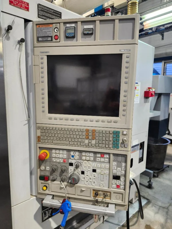
Tool wear is usually recognized not from a single sign but from several changes seen together: degraded surface quality, more burrs, changing part dimensions, rising spindle load, a change in the cutting sound, vibration, a change in chip shape or colour, and material welded onto the tool. The operator should know the normal sound and load values during production so that sudden changes are easier to spot.
The difference between dulling and breakage
In dulling the tool still cuts but the cutting edges are worn; the load usually rises slowly, the surface gradually degrades, the dimension drifts over time and burrs increase. In breakage part of the cutting edge or the tool body suddenly breaks off; the cutting sound changes at once, the spindle load rises or drops sharply, a deep mark appears on the part, and the program can continue in the air or with a broken tool.
What Is Spindle Load and How Is It Read?
The spindle load indicator shows how hard the main spindle motor is working during cutting; it can appear as a percentage, a bar graph, a power/torque value or a coloured indicator. For example, if an operation normally runs at about 35% load and the load gradually climbs to 60%, the tool may be worn, chips may be jamming or the cutting conditions may have changed. A single load percentage cannot be called normal or dangerous for all machines; the tool, material, spindle speed and machine power must be considered together.
Why does the spindle load rise?
Common causes: a dull tool, a broken insert, too much feed, too deep a cut, an unsuitable spindle speed, chips jamming around the tool, insufficient coolant, material harder than expected and contact with the part or fixture. If the load rises suddenly, stop the operation and do not continue before the cause is understood.
Why does the spindle load drop suddenly?
A sudden drop in load is not always a good thing. Possible causes: the tool has broken completely, the insert has come out, the tool is not reaching the part, the part has come out of the workholding, the tool has slipped up in the holder, or the program is running in the air at a wrong Z level. In an operation that should be removing material, a drop near zero must be checked.
How Is the Cutting Sound Interpreted?
A steady sound: the tool may be cutting regularly. A thin, continuous whine: a sign of vibration, too much tool overhang, an unsuitable speed or low rigidity. A metallic knock: can come from a broken insert, a loose tool, a loose part or interrupted, excessive load. The sound stopping suddenly: the tool may have broken or come out of the cut. When the operator notices a change in sound, they should not judge by ear alone; the spindle load, the part and the tool condition should also be checked.
What Does the Chip Appearance Tell You?
| Chip condition | Possible meaning |
|---|---|
| Regular, similar chips | Cutting may be stable |
| Very long chips | Chips not breaking or a jamming risk |
| Dust-like chips | The tool may be rubbing instead of cutting |
| Burnt or dark chips | The temperature may have risen |
| Chips welding to the tool | Cutting values, coating or lubrication may be unsuitable |
| Chips stopping suddenly | The tool may have broken or cutting stopped |
Chip colour alone is not conclusive; the material and the tool used must also be considered.
Signs on the Part Surface
Tool wear can leave a wavy surface, vibration lines, burn or colour change, an out-of-tolerance surface, excess burrs at the edges, irregularity at the pocket floor and shape distortion in circular machining. If the same mark appears at the same spot on every part, the program, the workholding and the tool path should also be checked.
Wear Signs by Tool Type
Milling tools: the corners of the cutting edges can round over, the coating can peel, small chips can form on the edges, the effective tool diameter can shrink and only one of the cutting edges may carry the load. On a multi-flute tool, one broken edge can significantly increase vibration.
Drills: the hole diameter changes, position deviation can appear, burrs at the hole mouth increase, the spindle load rises, the drill sound changes and material builds up in the flutes. If a drill breakage in a blind hole is not noticed, the following tap or reamer can hit the broken piece.
Taps: the tapping torque rises, the thread surface degrades, the thread gauge enters with difficulty, chip evacuation worsens and the risk of breakage increases. Tap wear cannot be corrected simply by changing the feed offset; the feed, pitch and spindle speed must stay synchronized.
First Steps When a Tool Breaks
- Stop the program safely.
- Check the position of the tool and the part.
- Record the alarm or the stopped program line.
- Do not open the door before the spindle has fully stopped.
- Clean the broken tool pieces with suitable equipment.
- Check the part, fixture and holder for damage.
- Investigate the cause of breakage.
- Do not continue the program without measuring the new tool.
If the tool is stuck inside the part, do not move the axes with random JOG.
Should the Tool Be Changed Without Finding the Cause?
Simply fitting a new tool is not enough. Check: has the tool life expired, are the cutting values suitable, is there runout in the holder, is the tool overhang too long, have chips jammed, is coolant reaching the right point, is there too much depth of cut in the program, has the part/workholding moved, has a broken tool been left inside the previous hole? If the cause is not corrected, the new tool can also break quickly.
Offset and wear check on the new tool
Even if the new tool is the same brand and size, the actual clamped length can differ. So re-measure the tool length, write it to the correct H offset, check the tool diameter and update the D offset if needed. An important point: do not blindly reuse the old wear value on the new tool. Because the old tool was worn, a correction may have been entered in the D or H wear field; the same correction can over-cut the part or shift the dimension the wrong way on a new tool. On the new tool, verify the geometry, adjust the wear to its initial state, run the first part in a controlled way and make a small correction after measuring.
Can a Part Machined with a Broken Tool Be Used?
The part must not be assumed good. Check: the dimension of the machined surface, hole depth, a broken tool piece inside a hole, cracks or marks on the surface, the area where the next tool will work and a broken piece inside the fixture. Especially if a drill or tap has broken, a piece may have been left inside the hole.
Where Should the Program Be Resumed?
Continuing directly from the line where the program stopped after a tool breakage is risky. The stopped line may be in the middle of a cut, inside a canned cycle, with G41/G42 compensation active, or in G91 incremental mode. For a safe restart, first determine the logic of the operation.
General safe resume sequence
- The cause of breakage is corrected.
- A new tool is fitted and measured.
- The part and fixture are checked.
- The start of the relevant operation in the program is found.
- The tool is moved to a safe Z position.
- The correct G54–G59 system is called; G90/G91, G17 and other modal codes are checked.
- Spindle speed and direction are re-issued; G43 and the correct H offset are enabled; coolant is turned on.
- Approach with Single Block and low Rapid Override; repeat the operation from a safe start point.
If a milling contour was left half-finished, trying to machine only the remaining part can cause an entry mark, a dimensional difference, a G41/G42 error or the tool starting inside the material. In most cases it is easier and safer to restart from the safe beginning of the relevant tool operation.
After drilling-cycle, tap and insert breakage
If a drill breaks in a G83 cycle, do not resume from the middle; first determine which hole broke, the depth it reached, whether the broken piece is still inside and whether the following holes have been machined. Do not send a new drill straight into the same hole at high feed. In a tap breakage, do not send a new tap into the same hole before the broken tap is removed; also recheck the tap-drill diameter, hole depth and the pitch–speed–feed relationship. On an indexable-insert mill, if one insert breaks the other inserts may also be damaged, the pocket seat crushed or the screw loosened; do not continue by only replacing the broken insert without checking the others.
Tool-Life Tracking
Tool life is not only the time until breakage. A tool should be changed based on a set part count, running time, cutting distance, spindle-load trend, dimensional change, surface quality or the tool manufacturer’s wear limit. Waiting for the tool to break increases production cost and part risk.
By part count: if a drill regularly runs about 800 holes, the change limit can be set on the safe side at 700 holes. But actual life depends on the material batch, coolant, hole depth and speed/feed; keep records and set the limit from real production data.
Tracking by spindle load
The load value of a sound tool in its first production run can be taken as a reference:
| Condition | Approx. load |
|---|---|
| New tool | 30% |
| Normal production | 32–38% |
| Onset of wear | 45% |
| Suspect condition | 55% and above |
This table is only to show the method; each operation should have its own normal load range established. The change in load can be more meaningful than the absolute number.
Tool-Breakage Sensors
Some machining centres have systems that check for tool breakage: a touch tool-setting probe, a laser tool-measuring system, spindle-load monitoring, tool-length checking and a macro-based tool-check cycle. These can check the presence of the tool, a large change in tool length and in some cases the tool diameter. However, they may not detect all breakages for certain — for example, only a single cutting corner of the tool may have broken.
A tool-breakage check can be made especially after critical operations: deep drilling, small-diameter drills, tapping, long and slender end mills, and operations where the next tool will enter the same hole. For example, a drill-breakage check before a tapping operation can prevent the tap from hitting a blocked hole.
Safe Checks the Operator Can Do
The operator can inspect the tool visually, change an insert, verify the correct tool and holder, re-measure the tool length, monitor the spindle load, evaluate the cutting sound and chips, check the part dimension and update the tool-life record. The operator must not change the spindle drive parameter, servo gains, load-alarm limits or sensor connections without authorization.
Common Mistakes
- Finishing the program even though the tool has broken (later operations can be wrong/dangerous)
- Only fitting a new tool without correcting the cause of breakage
- Not re-measuring the tool length
- Leaving the old wear value on the new tool
- Starting directly from the line where the program stopped
- Ignoring a sudden change in spindle load
- Constantly covering wear with an offset
- Not checking for a broken drill piece (the new drill/tap can break again)
Quick Check Table for Operators
| Symptom | First check |
|---|---|
| Spindle load rising slowly | Tool wear and chips |
| Load rose suddenly | Breakage, jamming or collision |
| Load dropped suddenly | Tool breakage or cutting in the air |
| Surface degraded | Tool, vibration and workholding |
| Burrs increased | Tool wear and cutting values |
| Cutting sound changed | Insert, tool tightness and load |
| Depth gradually increasing | Tool slipping in the holder |
| Tap breaks after drilling | Broken drill and tap-drill check |
Summary and Short Safety Sequence
Tool wear and breakage should be assessed together with the spindle load, cutting sound, chips and part-surface signs. The basic rule after a breakage is:
Stop → Check the broken tool and the part → Find the cause of breakage → Measure the new tool → Verify the offsets → Resume at low speed from the start of the operation.
Mentor CNC Disclaimer and Safety Notice
This content is prepared for general CNC machining centre operator training. Tool-breakage checking, spindle-load limits, program restart and tool-measuring methods differ between machines. If a tool is stuck inside the part or a mechanical collision has occurred, do not command random axis motion; follow the machine builder’s safe recovery procedure.