
Keeping a CNC machining centre accurate and reliable is not only the service engineer’s job. The simple checks an operator makes at the start of the shift, during production and at the end of the shift catch many faults early. The purpose of these checks is to start production safely, notice lubrication and air shortages, prevent chip build-up, spot tool and workholding problems, detect unusual noise or vibration early, and stop a small problem from turning into a major breakdown.
Daily Checks vs Technical Maintenance
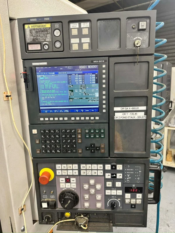
The operator’s job: check levels, watch for visible leaks, clean chips and dirt, record warning messages, notice changes in noise and vibration, report loose or damaged parts and perform the daily lubrication tasks in the manufacturer’s instructions.
The service engineer’s job: measurements in the electrical cabinet, drive and servo settings, parameter changes, dismantling the lubrication system, repairing hydraulic/pneumatic valves, adjusting spindle and axis geometry, and checking sensors and encoders. The operator must not touch the electrical cabinet or machine parameters for maintenance purposes.
When Are Daily Checks Done?
Daily checks should be carried out in three phases: at the start of the shift, during production and at the end of the shift. A short check only when the machine is switched on is not enough; coolant, chip build-up, tool wear and changes in noise must also be monitored while production continues.
Start of Shift: Surroundings and Inside the Machine
Before powering the machine, check the surroundings: is there oil or coolant on the floor, is there a slip hazard, has the chip trolley overflowed, are the air and electrical connections damaged, is anything blocking the doors, has a tool or gauge been left from the previous shift? Liquid on the floor is not only a cleaning issue — it can indicate an oil, hydraulic or coolant leak from the machine.
When the door is opened, check inside: a forgotten tool or vice handle on the table, a left-behind gauge/cloth/glove, heavy chips in the axis travel area, dirt on the door rails and way covers, a loose-looking fixture. A small item left inside can be thrown out when the spindle starts or coolant flows.
Central Lubrication Check
Axis guideways and ball screws are usually lubricated by an automatic central lubrication system. In the oil reservoir the operator should check: is the level above the minimum line, has it dropped abnormally since yesterday, is there dirt or water in the reservoir, is there a lubrication alarm, are there visible leaks in the lines? If the level is low, simply topping up and continuing may be wrong; the reason for the drop should also be investigated.
The right oil: do not add random oil to the reservoir. Use the class and viscosity specified by the manufacturer, clean. Mixing different oils can degrade lubrication, damage the pump and clog the lines. Do not overfill; overfilling can cause overflow, contamination and lubrication of electronic areas. Keep the level between the manufacturer’s marks.
If a lubrication alarm appears: record the message, check the level and visible connections, listen to the pump and inform qualified maintenance. Clearing the alarm and continuing is wrong; a lack of lubrication can cause guideway wear, ball screw damage and loss of positioning accuracy.
Air Pressure and the Air Preparation Unit
Many machining centres use compressed air for tool changing, spindle taper cleaning, tool clamp/unclamp, pneumatic doors and some fixtures. The operator should check the pressure on the gauge; the exact working pressure is the value specified by the manufacturer and must not be assumed the same on every machine.
Low air pressure can leave a tool change half-finished, prevent the tool from clamping correctly, stop the spindle taper from being cleaned and cause pneumatic fixture problems. Do not start the automatic cycle before the air pressure reaches its normal value. On the air preparation unit, watch for excess water in the filter bowl, the lubricator level, air-leak noise and cracked hoses.
Hydraulic Oil Check
On machines with a hydraulic system (tool clamp, pallet change, rotary-table lock, fixture clamp) check the oil level: is it normal, is the oil foamy or cloudy, is the temperature gauge normal, has the pump sound changed, is there a visible leak? If there is a hydraulic alarm or a serious leak, the machine must not be run.
Coolant: Level, Concentration and Nozzles
Check the coolant tank level before starting production. If the level is low, the pump can draw air, the cutting zone may not get enough coolant, and chip evacuation suffers. Adding only water lowers the concentration; adding only concentrate makes the mix too rich.
Concentration in water-based emulsions should be checked with a suitable instrument (refractometer). Too low: rust, poor lubrication, reduced tool life and bacterial growth. Too high: foaming, residue and a sticky film. The correct ratio follows the fluid manufacturer’s recommendation. Bad odour, heavy foam, colour change and sediment can indicate the fluid has gone off.
Nozzles must be aimed at the tool’s cutting zone before the program starts, with sufficient flow and no holes clogged by chips. If there is a separate spindle chiller, check its alarm, temperature and fan/pump operation; ignoring a chiller alarm can lead to thermal growth and spindle damage.
Around the Electrical Cabinet
The operator must not open the electrical cabinet. From outside, however, check: is the cabinet door closed, is the fan sound normal, do the filters look fully clogged, is there excessive heat or a burning smell, is there a temperature/fan alarm on the screen? If there is a burning smell, smoke or abnormal heat, cut the main power and inform qualified technical staff.
Machine Start-Up Sequence
The exact sequence differs by machine; the general logic is:
- Check the surroundings and inside the machine.
- Turn on the main electrical switch.
- Turn on the control / Power On button and wait for the system to fully start.
- Read the alarms and messages on the screen.
- Release the emergency stop safely; enable servo / Machine Ready.
- Send the axes to reference if required.
- Check lubrication, air and auxiliary units.
- Run a low-speed manual axis and spindle check.
If there is an alarm on the screen, do not just press Reset; record the full message, the time, which operation it occurred in and whether it repeats. During reference return the axes move in set directions, so keep clearance between tool and part and keep Rapid Override low. On machines that have been idle or are in a cold environment, use the manufacturer’s warm-up program if there is one; do not run the spindle and axes directly at high speed.
Spindle, Axis and Tool Magazine Checks
Before production a short low-speed spindle check can be made: is it turning in the right direction, is there unusual whine/vibration, is the no-load load high, is the speed stable? In JOG at low speed, observe short X, Y, Z axis moves: is the motion smooth, is there sticking/jerk, is anything binding under the way cover? The operator does not change axis/servo settings in this check, only records the symptom.
Inspect the tool magazine visually: are the holders seated correctly, is any tool loose or sagging, could a long tool hit a neighbour, has heavy chip/coolant built up, does the tool number match the record? Do not reach into the magazine or tool-change arm while powered.
The spindle taper and tool holder must be clean; chips, oily dirt, rust or dents on the taper cause the tool to seat with runout. When cleaning, the spindle must be fully stopped, use a suitable clean cloth, and do not damage the taper with abrasives. The pull stud must match the machine standard, not be loose and be free of cracks.
Vice, Fixture and Table Cleaning
At the start of each shift, visually check the vice mounting bolts, clamps, stops and hydraulic/pneumatic connections. Chips under the part spoil the clamping; even a small chip can make the part sit at an angle and throw off all dimensions. Clear the table and T-slots of chips, dried coolant and dirt, but do not use sharp tools that scratch the metal surfaces.
Chip Conveyor and Chip Cleaning
The chip conveyor can be run briefly before production: is the direction correct, is the chain/belt catching, is there unusual noise, are long chips wrapped in the mechanism? Chip build-up can damage way covers, block coolant return channels, seat the part wrongly and create a fire risk.
Chip-cleaning safety: the spindle and axis motion must be stopped, the automatic cycle must not be active, use a suitable hook and brush, do not touch sharp chips with bare hands and do not disable the door safety. Do not remove chips around a rotating tool by hand or with a cloth. Blowing chips with compressed air onto the guideways, measuring systems, spindle interior or electrical areas is not appropriate.
Doors, Safety and Emergency Stop
Does the door open and close easily, does the lock work, has the safety switch been disabled, is there a crack in the window? Door safety systems must not be bridged or disabled. The emergency stop button must be accessible, undamaged and free of foreign objects; test it per the manufacturer’s procedure, not at random during production.
What to Monitor During Production
Checking does not stop once production starts. The operator should follow spindle and axis loads, air pressure, lubrication messages, coolant flow, tool noise, vibration, chip form and cycle time. Sudden changes are often an early sign of tool wear or chip jamming.
Unusual sounds: a continuous whine can mean vibration/wrong speed/long tool; a metallic knock a loose tool/broken edge/workholding problem; an intermittent pump sound a low fluid level; a friction sound in axis motion chips under the way cover or a lubrication problem. On new vibration the operator first checks the tool, holder, part and cutting values; does not change servo/spindle settings. Do not continue the cycle before the cause is understood.
End-of-Shift Cleaning and Shutdown Sequence
General end-of-shift steps: finish the program safely, move the tool and axes to a safe position, stop the spindle and coolant, run the chip conveyor for an appropriate time, clean the table/fixture/cabin, watch for leaks, put away tools and gauges and log any problems.
Shutdown sequence (general approach): stop and reset the program, fully stop the spindle, turn off coolant and auxiliary systems, move the axes to the manufacturer’s park position, check alarms, apply CNC Power Off and wait for the control to shut down, then turn off the main switch if required. Do not cut the main switch before the control has finished shutting down. The park position aims to keep the tool away from the part, let the door open easily and keep the machine safe at the next start-up. If the machine will be idle for a long time, extra steps such as protective oil, rust prevention and shutting energy lines may be needed.
Situations the Operator Must Not Handle
Call qualified technical staff in these cases: an electrical or burning smell, a drive/servo alarm, a repeating lubrication alarm, a large hydraulic/oil leak, a metallic sound from the spindle, a tool changer stopping half-way, an axis moving with binding, excessive heat in the electrical cabinet, a safety system not working, smoke or sparks. The operator must not change an alarm, parameter or sensor connection to hide a fault.
Daily Operator Check Form
| Check point | Status |
|---|---|
| Surroundings and cabin clean | OK / Not OK |
| No leak on the floor | OK / Not OK |
| Central lubrication level | Normal / Low |
| Hydraulic oil level | Normal / Low |
| Air pressure | Normal / Low |
| Coolant level and flow | Normal / Weak |
| Chip conveyor | Normal / Faulty |
| Door and lock system | Normal / Faulty |
| Spindle and axis noise | Normal / Abnormal |
| Tool magazine | Normal / Faulty |
| Panel warnings / visible leak | None / Present |
Daily, Weekly and Periodic Maintenance
Daily operator checks: levels, cleaning, noise, vibration, alarms, leaks, tool and workholding. Weekly checks (per shop procedure): external filter checks, conveyor check, short test moves, comparing records. Monthly and longer maintenance (qualified staff): connections, filter changes, precision measuring systems, electrical checks, geometric tests. CNC maintenance is divided into daily, weekly, monthly, six-monthly and yearly intervals.
Common Daily Maintenance Mistakes
- Starting production without checking the oil level
- Topping up with the wrong oil or overfilling the reservoir
- Changing tools at low air pressure
- Adding only water to the coolant (concentration and rust protection suffer)
- Blowing chips under the way covers with compressed air
- Resetting an alarm without recording it
- Accepting an abnormal sound as normal
- The operator opening the electrical cabinet
- Cutting the main switch without following the shutdown sequence
Quick Start-Up Checklist for Operators
- Are the surroundings and cabin clean, is there a leak on the floor?
- Are the central lubrication and hydraulic oil levels normal?
- Is the air pressure adequate, is the coolant sufficient?
- Is the tool magazine tidy, are the table and fixture secure?
- Is there an active alarm, is the axis/spindle noise normal?
- Do the door and safety lock work, is the chip conveyor normal?
The automatic cycle must not be started before these checks are complete.
Summary
This guide covered the purpose of daily operator maintenance, the split between operator and service tasks, start-of-shift checks, central lubrication and hydraulic oil, air pressure, coolant level and concentration, spindle/axis/magazine checks, chip cleaning, the end-of-shift shutdown sequence and the situations the operator must not handle. Regular daily checking is the most economical insurance for machine life and part quality.
Mentor CNC Disclaimer and Safety Notice
This content is prepared for general CNC machining centre operator training. Oil types, air pressure, the start-up/shutdown sequence, maintenance intervals and the park position differ between machine builders. Follow the maintenance manual and the shop’s safe-working procedures; electrical, servo, spindle, hydraulic and parameter work must only be done by qualified technical staff.