
This guide collects, on a single page, the panel keys of the Mitsubishi M70/M700 control and the G codes used in the machining-center system. It has two main parts: (1) the keys on the control panel and (2) the M70/M700 machining-center G codes. An important note: even if the Mitsubishi M70/M700 control is the same, the physical keys, soft-key names and screen menus can vary by the machine builder’s PLC, panel and software settings. Options like OFFSET, WORK OFFSET, PROGRAM, FILE, COPY, MEASURE and CALC can be a bottom soft key rather than a separate key on some machines.
Part 1 — The keys on the control panel
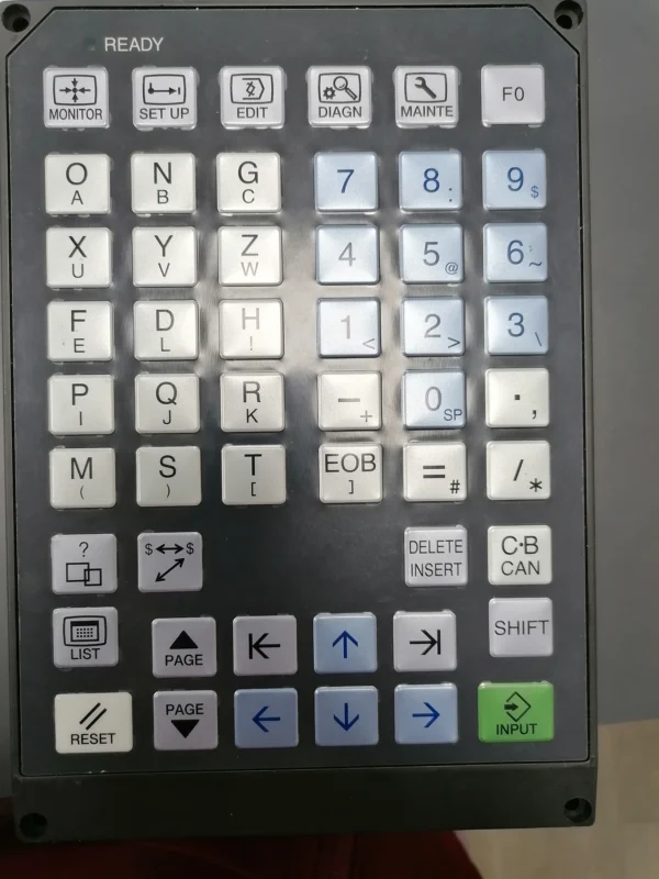
1. Screen-select keys
MONITOR — Monitors the state of the machine and the running program. The screen usually shows the active program number, the running line, X/Y/Z positions, spindle speed, feed, active tool, active M/S/T/B commands, alarm/stop messages and remaining travel. It is the most-used screen while running; in Program Restart, MONITOR is entered first, then the RESEARCH menu. The counter fields (current/workpiece/machine/program position, remaining command, restart position, etc.) can be set with user parameters.
SETUP — Prepares the data and user settings needed before machining (tool offsets, workpiece zeros, counters, common variables, user parameters, I/O and program-transfer device selection). It must not be confused with the service parameter screen; the operator should change only the values they are authorized for.
EDIT — Creating and editing a CNC program: opening a new program, writing/inserting a line, changing a wrong line, deleting a line/program, searching and copying a program. Changes on the EDIT screen while a program runs must be made carefully. Start-from-a-specific-line uses the MONITOR → MODE AUTO → EDIT sequence.
DIAGNOSIS — Checks the machine’s I/O and system state: PLC inputs/outputs, limit signals, sensor states, Cycle Start and door signal, tool magazine signals, servo/spindle states, communication info. It is mostly for fault-finding and technical service; the operator can read the values but must not force signals on/off.
MAINTENANCE — Reaches maintenance and service operations: parameters, system info, backup, PLC/servo/spindle info, battery state, version info, alarm history. This section is more a technical-service screen than an operator one; parameter changes can change how the machine works. The Mitsubishi manual states that the machine builder’s instructions take priority over the general control manual.
OFFSET / TOOL OFFSET — Views and enters tool offset values: tool length, tool radius/diameter, Geometry, Wear, H and D offset numbers. For example T1→H1, T2→H2; when G43 H2 is written, the tool length in the H2 field is used. The tool diameter/radius is usually held in the D field.
WORK OFFSET — Views and sets the workpiece coordinate zeros: G54–G59 coordinate systems and X, Y, Z (and A/B/C if present) in each. For example G54 the first vise, G55 the second vise, G56 a separate fixture. The Mitsubishi programming manual defines G54–G59 as separate workpiece coordinate systems.
PROGRAM — Views, selects and manages CNC programs: opening the program list, searching by O number, selecting, viewing content, editing, resetting to the start, deleting/copying. E.g. O1000, O1001, O2000 are listed here. FILE — Manages file operations between NC memory and external devices (NC MEMORY, CF CARD, IC CARD, USB, computer, DNC): getting/sending/copying/deleting a program, renaming a file, viewing device content.
2. Data-entry and editing keys
INPUT — Makes the control accept the typed value or selected operation: entering a parameter/tool offset/G54 value, accepting a program number, starting a Program Restart search, running a selected M/S/T command. When INPUT is pressed on the Program Restart MSTB History screen, the selected command can run — e.g. M3 may start the spindle, M8 may turn on the coolant.
INSERT — Adds a new character, word or program line; does not change the existing line. E.g. N25 G40 G49 G80; can be inserted between N20 G17 G90; and N30 M30;. ALTER — Replaces the existing program word/line with a new one; the correct line is written and ALTER is used (CHANGE/REPLACE/MODIFY on some panels). DELETE — Deletes the selected character, word, line or file; its effect depends on the screen you are on (a character/command/line inside the program; the whole program in the program list). So the cursor position must be checked.
EOB (End of Block) — Signals that the program line has ended; shown as ; on screen (e.g. N10 G21;). RESET — Cancels the active operation, resets the alarm or stops program execution; not the same as FEED HOLD (FEED HOLD pauses temporarily, RESET can cancel). The M700 Handbook states that after RESET the program execution position can return to the program start. SHIFT — Selects the second character/function on a key (like the computer Shift key). CAN (Cancel) — Clears an entry being typed that has not yet been confirmed with INPUT; does not cancel a running program (use RESET for that).
Arrow keys — Move the cursor on screen: navigating between program lines, selecting from an M/S/T list, selecting a parameter/G54 field, selecting a program in the file list. In Program Restart Type 3 the wanted line is reached with the arrow keys. Page keys (PAGE UP/DOWN) — Change pages in long lists and screens. Arrow keys move line by line, page keys screen by screen.
3. Bottom soft keys
The function of soft keys is not fixed; whatever task the text at the bottom of the screen shows, the key does that task at that moment (the same physical key can be SEARCH on one screen and COPY on another).
SEARCH — Searches for specific information in a program/file (O program number, N sequence number, a specific command, a file name). TOP SEARCH — Finds the start of the program/file; used to reset a program to the start and to select the program in Restart Type 2. FILE SET — Transfers the program selected from the file list into the relevant input field (reduces manual-typing errors). RESEARCH — Researches the stopped point for Program Restart; usually the MONITOR → RESEARCH → TYPE 1/TYPE 2 sequence (different from the normal search key).
TYPE 1 — Lets the control find where the program stopped automatically; the operator does not enter a program/N/line/block number. The source defines Type 1 as the easier and safer restart method. TYPE 2 — Sets the program, line or block chosen by the operator as the restart point; the program is selected, the line/block is entered, the search is started. It needs more program knowledge than Type 1 and has a higher risk of selecting the wrong line.
MSTB HISTORY — Shows the auxiliary command history the program ran up to the restart point: M (auxiliary commands), S (spindle speed), T (tool), B (second auxiliary functions). E.g. past commands like S1500, T6, M3, M8 may be seen; the operator selects the needed ones. Remember that the selected command can run the moment INPUT is given. COPY — Copies a program/file elsewhere (MEMORY→USB, USB→MEMORY, MEMORY→CF CARD, O1000→O1001); the source and target device must not be confused.
INPUT (soft key) — Similar to the physical INPUT, works by screen: getting data from an external device into NC memory, loading a selected file, writing a measured value into the table, confirming the selection. OUTPUT — Sends data inside the CNC to an external device (NC MEMORY→USB/CF CARD/computer): program/tool/parameter backup, exporting workpiece zeros. DELETE (soft key) — Depending on the screen, deletes a file/program/line or clears the selected offset value.
MEASURE — Computes and saves a tool or workpiece offset value based on the current machine position: tool length measurement, getting the G54 X/Y/Z value, saving a probe result. E.g. if the tool is touched to the part top and MEASURE is applied with Z0, the control can compute the G54 Z shift (behavior varies by builder). CALC (Calculate) — Applies a math operation to the entered/current value: adding/subtracting, accounting for an edge-finder radius or gauge thickness, finding the midpoint of two edges. It must not be used without checking the sign direction.
Panel keys quick-reference table
| Key | Basic function |
|---|---|
| MONITOR | Monitors operation and the active program |
| SETUP | Reaches user and machining settings |
| EDIT | Creates and edits a program |
| DIAGNOSIS | Shows signal and system states |
| MAINTENANCE | Opens service and maintenance screens |
| OFFSET | Shows tool offsets |
| WORK OFFSET | Shows G54–G59 part zeros |
| PROGRAM | Selects and manages programs |
| FILE | Manages file and device operations |
| INPUT | Confirms the value or operation |
| INSERT | Adds new data |
| ALTER | Changes existing data |
| DELETE | Deletes the selected data |
| EOB | Ends the program line |
| RESET | Cancels the operation or program |
| SHIFT | Selects the second character |
| CAN | Cancels an unentered value |
| SEARCH | Searches a program or file |
| TOP SEARCH | Finds the start of the program |
| FILE SET | Transfers the selected file to the input field |
| RESEARCH | Enters restart-point research |
| TYPE 1 | Finds the restart point automatically |
| TYPE 2 | Operator sets the restart point |
| MSTB HISTORY | Shows past M, S, T and B commands |
| COPY | Copies a file or program |
| OUTPUT | Sends data from the CNC to an external device |
| MEASURE | Computes and saves a measurement value |
| CALC | Does numeric calculation/correction |
Part 2 — Mitsubishi M70/M700 G codes
The main G codes given for the machining-center system in the programming manual are below. Some codes are optional; depending on the control software and the builder’s setting, they may not be usable. The manual also states that if more than one G code from the same group is written, the last one written is valid, and that the machine builder can define special G-code macros.
Motion and interpolation codes
| G code | Function |
|---|---|
| G00 | Rapid positioning |
| G01 | Linear cutting move |
| G02 | Clockwise circular interpolation |
| G03 | Counter-clockwise circular interpolation |
| G02.1 / G03.1 | Type 1 spiral or conical interpolation |
| G02.3 / G03.3 | Exponential function interpolation (positive/negative) |
| G02.4 / G03.4 | Three-dimensional circular interpolation |
| G05 | High-speed machining or high-accuracy control |
| G05.1 | High-speed high-accuracy control or spline function |
| G06.2 | NURBS interpolation |
| G07 | Hypothetical axis interpolation |
| G07.1 / G107 | Cylindrical interpolation |
| G12.1 / G112 | Polar coordinate interpolation on |
| G13.1 / G113 | Polar coordinate interpolation cancel |
Dwell and motion-control codes
| G code | Function |
|---|---|
| G04 | Dwell for a set time |
| G08 | High-accuracy control |
| G09 | Exact stop at a block end |
| G22 / G23 | Pre-travel stroke/motion check on/cancel |
| G60 | Unidirectional positioning |
| G61 | Exact-stop check mode |
| G61.1 | High-accuracy control on |
| G61.2 | High-accuracy spline interpolation |
| G62 | Automatic corner override |
| G63 | Tapping mode |
| G63.1 / G63.2 | Normal / reverse synchronous tapping |
| G64 | Continuous cutting mode |
Plane and measurement-system codes
| G code | Function |
|---|---|
| G15 / G16 | Polar coordinate command off / on |
| G17 | Select the X-Y plane |
| G18 | Select the Z-X plane |
| G19 | Select the Y-Z plane |
| G20 / G21 | Inch / millimeter measurement system |
| G90 / G91 | Absolute / incremental coordinate programming |
Reference and coordinate codes
| G code | Function |
|---|---|
| G27 | Check whether the reference position is correct |
| G28 | Return to the first reference point |
| G29 | Return to the start position after G28 |
| G30 | Return to the 2nd/3rd/4th reference point |
| G30.1–G30.6 | Return to defined tool-change positions |
| G52 | Create a local coordinate system |
| G53 | Move in the machine coordinate system |
| G54–G59 | Workpiece coordinate systems 1–6 |
| G54.1 | Extended workpiece coordinates |
| G92 | Set the coordinate system |
| G92.1 | Workpiece coordinate system preset |
Tool compensation codes
| G code | Function |
|---|---|
| G38 / G39 | Radius compensation vector / corner arc |
| G40 | Cancel cutter radius compensation |
| G41 / G42 | Radius compensation — left / right of travel |
| G43 / G44 | Positive / negative tool length compensation |
| G49 | Cancel tool length compensation |
| G43.1 | Tool length compensation along the tool axis |
| G43.4 / G43.5 | Tool center point control Type 1 / Type 2 |
| G45 / G46 | Increase / decrease tool position offset |
| G47 / G48 | Double increase / decrease the offset |
| G40.1 / G41.1 / G42.1 | Normal-line control cancel / left / right |
Normal-line control (G40.1/G41.1/G42.1) is optional on some machines; the M700 Handbook states that when this feature is absent, these commands cause a program error.
Scaling, mirror and coordinate rotation
| G code | Function |
|---|---|
| G50 / G51 | Cancel / turn on scaling |
| G50.1 / G51.1 | Cancel / turn on G-code mirror image |
| G68 / G69 | Coordinate rotation / 3D coordinate conversion on / cancel |
Special cutting and drilling cycles
| G code | Function |
|---|---|
| G12 / G13 | Clockwise / CCW circular pocket cutting |
| G34 | Bolt-hole circle special cycle |
| G35 | Angled-line special cycle |
| G36 | Arc-shaped special cycle |
| G37 | Automatic tool length measurement |
| G37.1 | Grid-shaped special cycle |
| G70–G79 | User/builder canned cycles |
| G73 | Short-retract (step) drilling |
| G74 | Reverse tapping cycle |
| G75 | Circular cutting cycle |
| G76 | Fine boring cycle |
| G80 | Cancel the active drilling cycle |
| G81 | Simple drilling or center drilling |
| G82 | Dwell drilling or flat counterbore |
| G83 | Peck deep drilling |
| G84 | Tapping |
| G85 | Boring or hole enlarging |
| G86 | Boring with spindle stop |
| G87 | Back boring |
| G88 | Boring with manual retract |
| G89 | Dwell boring |
| G98 / G99 | Return to initial / R level at cycle end |
Feed and spindle codes
| G code | Function |
|---|---|
| G93 | Inverse-time feed |
| G94 | Feed per minute |
| G95 | Feed per revolution |
| G96 / G97 | Constant surface speed control on / cancel |
G96 and G97 are more common on lathe systems but may appear in the manual’s common features; the machine model must support this feature.
Programmed data input and macro codes
| G code | Function |
|---|---|
| G10 / G11 | Enter parameter/offset/coordinate data from the program / cancel |
| G65 | One-shot user macro call |
| G66 / G66.1 | Modal user macro call A / B |
| G67 | Cancel modal macro call |
| G100–G255 | Parameter-definable user G-code macros |
Measuring codes
| G code | Function |
|---|---|
| G31 | Skip or measurement move |
| G31.1 / G31.2 / G31.3 | Multi-step skip input 1 / 2 / 3 |
These codes are generally used in probe, tool-measuring-sensor or contact-detection operations.