
The drawing of a sheet-metal part gives the outside dimensions of the bent part, but what the laser, shear or punch has to cut is the flat pattern: the length of the sheet before bending. The two are not equal. In the bend zone the inside of the sheet is compressed and the outside is stretched, and the difference depends on sheet thickness, inside radius and bend angle. Starting from the outside dimensions on the drawing, this calculator gives the bend allowance (BA) for each bend, the setback to deduct from each flange, and the total flat length of the part.
The method is the K-factor method taught in technical drawing courses: BA = π × (R + K × T) × A / 180. The tool picks K from the R/T ratio automatically, or you can enter the K-factor your CAD system or tooling supplier gives you.
1. Sheet and bend data
Enter all dimensions in millimetres. Use a dot or a comma for decimals.
2. Flange outside dimensions
Enter the outside dimensions from the drawing in order. End flanges are bounded by one bend, inner flanges by two; the tool deducts accordingly.
What happens when sheet is bent: the neutral axis and the K-factor
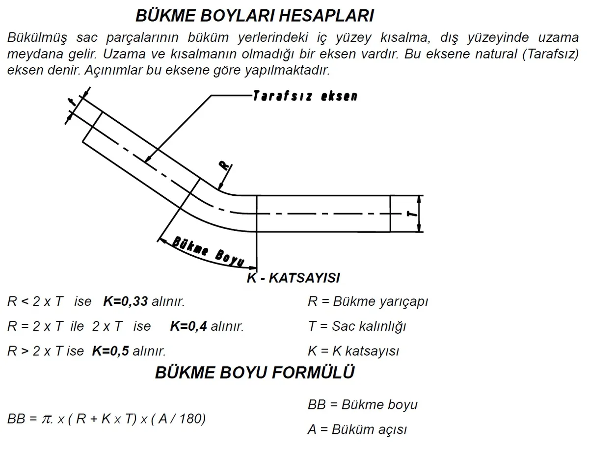
When sheet is bent, the inside surface of the bend zone is compressed and shortens while the outside surface is stretched and lengthens. Between them lies a layer whose length does not change at all: the neutral axis. The flat length is calculated along that axis, because it is the only length that is the same before and after bending.
The neutral axis is not in the middle of the sheet; it shifts towards the inside surface. The distance from the inside surface to the neutral axis, divided by the sheet thickness, is the K-factor. K = 0.5 is the theoretical case with the axis exactly in the middle; in practice it comes out between 0.3 and 0.5. The smaller the radius relative to the thickness, the further the axis moves inward and the smaller K becomes.
The bend allowance formula
BA = π × (R + K × T) × A / 180
- BA — bend allowance: the arc length of the bend zone measured on the neutral axis (mm)
- R — inside bend radius (mm), set by the punch tip and the die opening
- T — sheet thickness (mm)
- K — K-factor (dimensionless)
- A — bend angle in degrees: how far the sheet is rotated from flat (90 for a 90° bend)
(R + K × T) is the radius of the neutral axis; π × A/180 converts the angle into arc length. For 90° the formula shortens to BA = π × (R + K × T) / 2.
How to choose the K-factor
| Ratio | K | Notes |
|---|---|---|
| R < 2 × T | 0.33 | Sharp bend, axis close to the inside. Most press-brake work is here. |
| 2 × T ≤ R < 4 × T | 0.40 | Medium radius |
| R ≥ 4 × T | 0.50 | Large radius, axis in the middle |
These are the general rules found in textbooks and in the DIN 6935 approach. Material (mild steel, stainless, aluminium), grain direction and die opening all change K. For production work the right way is to bend a test piece, measure K for your own machine and use that value in CAD.

How to find the flat length, step by step
- Take the outside dimensions of the flanges from the drawing (outside-to-outside of the bent part).
- Work out the setback to deduct per bend: for a 90° bend it is R + T; in general (R + T) × tan(A/2).
- Find the flat length of each flange: deduct the setback once from an end flange, twice from an inner flange.
- Calculate BA for each bend.
- Flat length = sum of flange flats + sum of bend allowances.
Example 1: L bracket (27 × 15, T = 3, R = 3)
R = 3 and T = 3 → R < 2T → K = 0.33. BA = π × (3 + 0.33 × 3) × 90/180 = π × 3.99 × 0.5 = 6.27 mm (6.264 with π = 3.14). Flanges: 27 − (3 + 3) = 21 and 15 − 6 = 9. Flat length = 21 + 9 + 6.27 = 36.27 mm.

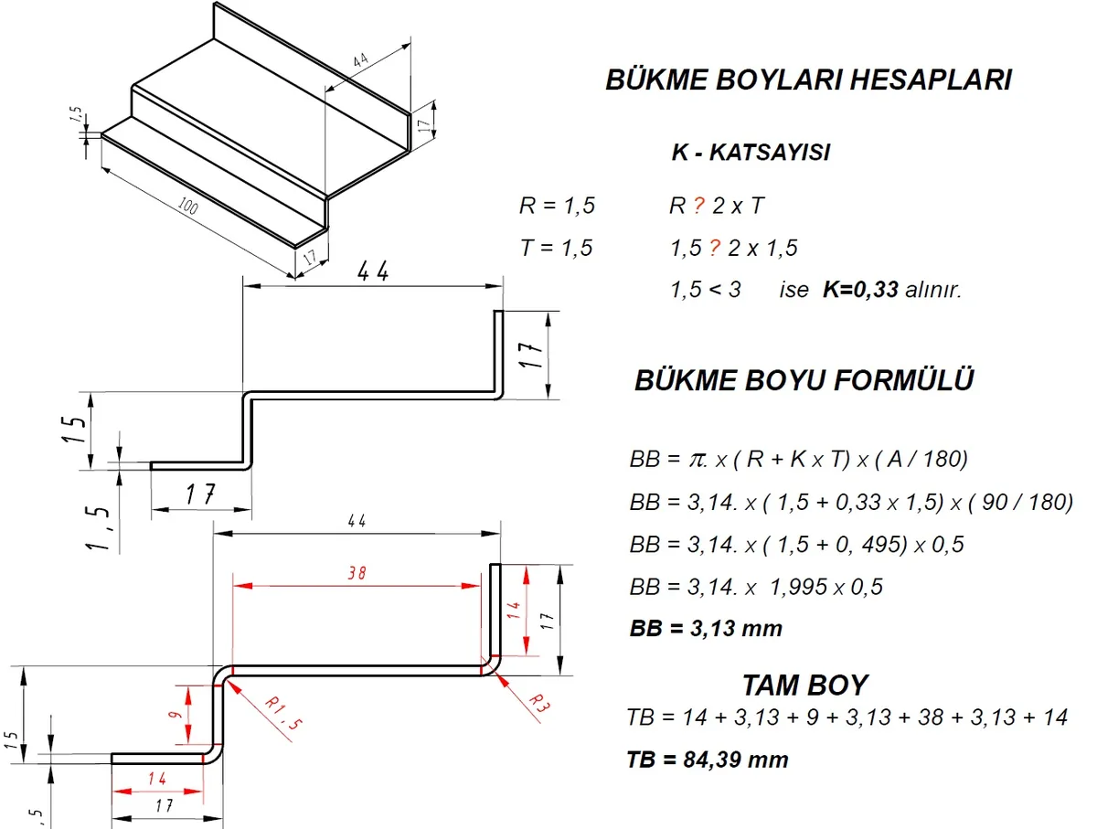
Example 2: Z profile (T = 1.5, R = 1.5, three bends)
K = 0.33. BA = π × (1.5 + 0.33 × 1.5) × 0.5 = 3.13 mm. Outside dimensions 17 / 15 / 44 / 17; setback = R + T = 3. Flats: 17 − 3 = 14, 15 − 6 = 9, 44 − 6 = 38, 17 − 3 = 14. Total = 14 + 9 + 38 + 14 + 3 × 3.13 = 84.4 mm.
Example 3: U channel (330 / 460 / 330, T = 3, R = 3)
BA = 6.27 mm. Flats 324, 448, 324. Total = 324 + 448 + 324 + 2 × 6.27 = 1108.5 mm. In the tool, select "Number of bends 2" and enter the three flanges to get the same result.

Bend allowance, bend deduction and setback: keep the terms apart
- Bend allowance (BA): the length of the bend zone in the flat pattern. It is added.
- Setback: the distance from the outside corner to the start of the bend, (R + T) × tan(A/2). It is deducted from each flange.
- Bend deduction (BD): the single figure deducted from the sum of two outside dimensions to get the flat length: BD = 2 × setback − BA. Some textbooks and CAD systems work this way; the result is identical.
The tool reports all three, so whichever table you compare against, you are speaking the same language.
Dimensioning the flat pattern drawing
The flat pattern is drawn as a separate single-view drawing for the laser or punch, with a thickness note. Hole positions are dimensioned at their location before bending; bend lines are shown as thin chain lines. A hole too close to a bend line (closer than about 2T + R from the bend as a rule of thumb) distorts during bending and is then drilled after forming instead.

Frequently asked questions
I do not know the inside radius. What should I enter?
In air bending on a press brake the inside radius comes out at roughly 15–20 % of the die opening (V); with the usual V = 8T die that is close to R = T. If you have no better figure, enter R = T and verify on the first part.
Should I use K = 0.33 or 0.5?
0.33 for sharp bends (R < 2T), approaching 0.5 for gentle, large-radius bends. On 3 mm sheet the difference is about 0.8 mm per 90° bend — more than 3 mm of error on a four-bend box. For production, measure K on a test bend first.
Does the tool accept inside dimensions?
No, it expects outside dimensions. If the drawing gives inside dimensions, add one T per bend bounding that flange to convert it to an outside dimension.
What changes for angles other than 90°?
The setback becomes (R + T) × tan(A/2) and flange dimensions are taken to the virtual corner where the two outside faces meet. For angles below 90° the setback shrinks; above 90° it grows quickly — at a 135° bend it is 2.4 times (R + T).
My CAD system gives a different result. Which is right?
Both are right for their own K. SolidWorks, Inventor and similar programs use a default K = 0.5 or a material table. Enter the same K manually and the tool returns the same figure. What is right on the shop floor is the value you measure on a test bend.
Mentor CNC note and disclaimer
This tool calculates a theoretical flat length by the K-factor method; material grade, grain direction, die opening and bending method (air bending, bottoming, coining) change the result. For toleranced work, bend a test piece and determine the K-factor for your own machine. Mentor CNC accepts no responsibility for parts cut on the basis of this calculation or for their commercial consequences.