
A large share of the parts that reach a machine shop are weldments: machine frames, bases, fixtures, flanged pipes. Their drawings do not show every weld bead; each joint is described by a welding symbol. If you cannot read the symbol you do not know where the part is solid, where the groove is, or which face is machined after welding. This page explains welding symbols to ISO 2553 as far as a CNC operator and a draughtsperson need them.
What you will learn: The five parts of a welding symbol (arrow, reference line, identification line, symbol, tail) · Elementary symbols (square, V, bevel, Y, U, fillet, backing run) · Supplementary symbols (flush, convex, concave) · The difference between a, z and s · Intermittent welds written n × l (e) · Weld-all-round and field-weld marks · ISO 4063 process numbers in the tail
What a welding symbol is made of
A welding symbol has five parts, and each has a fixed place:
- Arrow line: its tip touches the joint. For joints where only one member is prepared (a bevel weld, for example) the arrow points at the member to be prepared.
- Reference line: the horizontal continuous line the arrow is attached to. Symbols sit above or below it.
- Identification line: a dashed line parallel to the reference line (“system A” in ISO 2553). A symbol on the continuous-line side means the weld is on the arrow side; on the dashed-line side it means the other side. For symmetrical (double-sided) welds the dashed line is omitted.
- Elementary symbol: describes the cross-section of the weld (V, square, fillet…).
- Tail: the fork at the end of the reference line, carrying the process, quality level, position and filler metal. It is left out when there is nothing to say.
The American system (AWS A2.4) has no dashed line: “arrow side” is below the reference line and “other side” is above it. ISO 2553:2019 defines both systems (A and B) and the title block must state which one the drawing uses. In Turkey and across Europe the dashed-line system A is the usual one.
Elementary weld symbols
An elementary symbol looks like the cross-section of the weld, so when you see it you should be able to picture the edge preparation. That “preparation” is the groove machined into the plate edge before welding — very often by milling, turning or chamfering, which is where the CNC operator comes in.
| Symbol | Name | When it is used |
|---|---|---|
| ‖ | Square butt weld | Thin sheet, no edge preparation |
| V | Single-V butt weld | Medium plate, both edges bevelled |
| half V | Single-bevel butt weld | Only one member is bevelled; the arrow points at it |
| Y | Single-V with broad root face | Thicker plate, a root face is left below the V |
| half Y | Single-bevel with broad root face | One-sided bevel plus root face |
| U / half U (J) | Single-U butt weld | Very thick plate, less filler metal |
| △ (right triangle) | Fillet weld | T-joints and lap joints — the symbol you will see most in the shop |
| ◡ (half circle) | Backing run | Root pass made from the back of the main weld |
| // | Steep-flanked weld | Butt joint with steep, nearly parallel edges |

Supplementary symbols: the weld surface
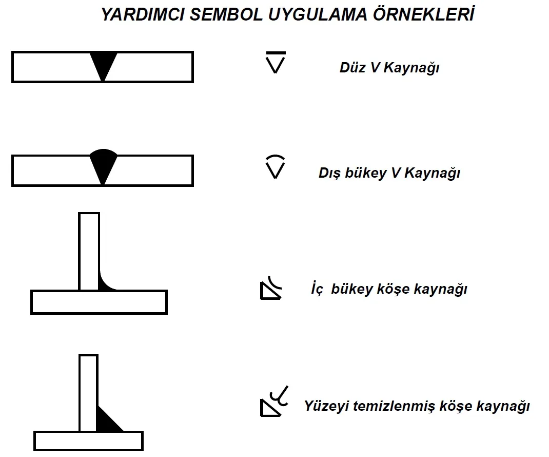
Small marks added on top of the elementary symbol say how the outer surface of the weld is to be finished: a straight line = flush (ground or dressed flat), a convex arc = raised bead, a concave arc = hollow bead. A small curve added to the toe of a fillet symbol means the toes are to be blended smoothly. For the CNC operator the message is this: a butt weld marked “flush” may be a surface that is machined later — check the drawing for a machining allowance on it.
Above or below the reference line?
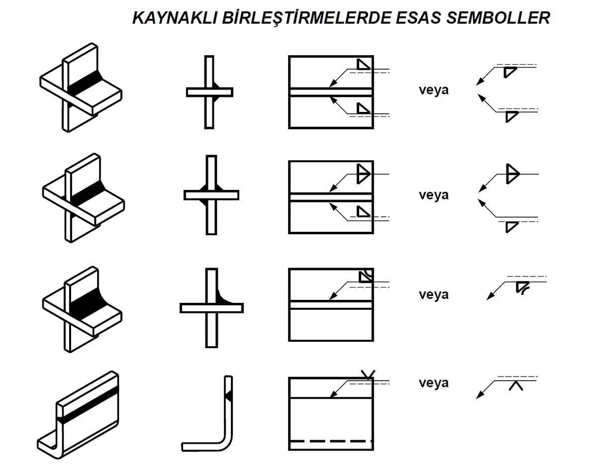
This is where most reading errors happen. The rule: a symbol on the continuous reference line side means the weld is on the side the arrow points to; on the dashed line side it is on the opposite side. The examples below show the same T-joint welded on the arrow side, on the other side and on both sides. Two symbols at once, above and below (a double-V, i.e. an X weld, for example) mean the joint is welded from both faces; the dashed line is then left out.

Weld dimensions: what a, z and s mean
The cross-section dimension is written to the left of the symbol, the length dimension to the right. The cross-section is given with one of three letters:
| Letter | Meaning | Where |
|---|---|---|
| s | Depth of penetration: the minimum distance from the plate surface to the deepest point the weld reaches | Butt welds (square, V, Y), e.g. s6 |
| a | Throat thickness: the height of the largest isosceles right triangle that fits in the weld section | Fillet welds, e.g. a5 |
| z | Leg length: the side of that same triangle | Fillet welds, e.g. z7 |
The same fillet weld can be written either way; the relation is a ≈ 0,7 × z (z ≈ 1,4 × a). “a5” is roughly the same weld as “z7”. Whichever letter the drawing uses is the one the welder measures, and fillet gauges are marked for both.

Intermittent welds, weld-all-round and field welds
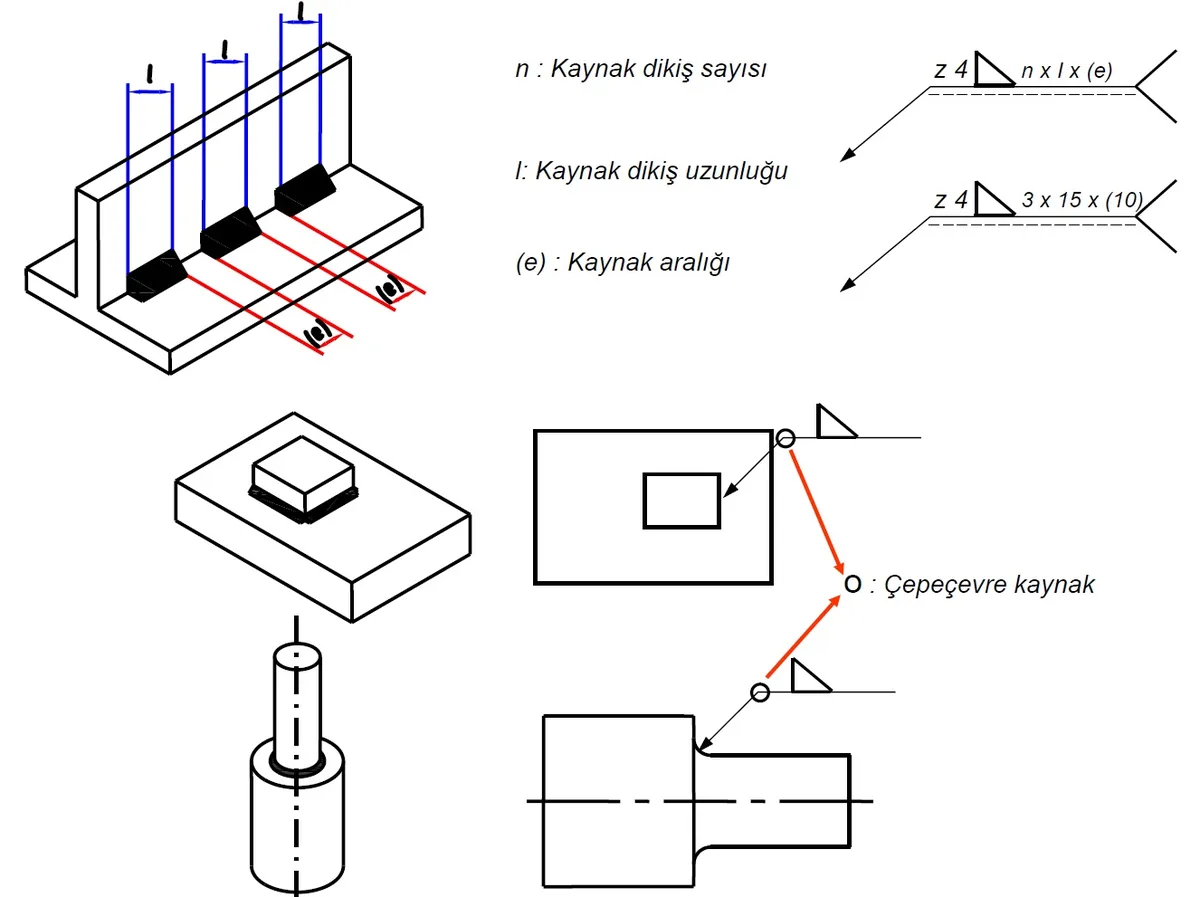
The expression n × l (e) to the right of the symbol describes an intermittent weld: n is the number of weld elements, l the length of each, (e) the gap between them. Example: z4 △ 3 × 15 (10) = three fillet welds with a 4 mm leg, each 15 mm long, with 10 mm gaps. Nothing on the right means the weld is continuous along the whole joint.
A small circle at the junction of the arrow and the reference line means the weld goes all round the part — standard on flange-to-pipe joints. A flag at the same point means the weld is made on site (a field weld), not in the shop. Whether the flag points up or down does not change its meaning.
What goes in the tail: ISO 4063 process numbers
The fork at the end of the reference line carries, separated by slashes and in this order: 1) the welding process number (ISO 4063), 2) the quality / acceptance level (ISO 5817 for steel — B, C, D; ISO 10042 for aluminium), 3) the welding position (ISO 6947 — PA, PB, PF…), 4) the filler metal (ISO 2560 for covered electrodes, ISO 3581 for stainless electrodes, ISO 544 for general delivery conditions). The numbers you will meet most often:
| No | Process | Shop name |
|---|---|---|
| 111 | Manual metal arc welding with covered electrode | Stick welding, MMA / SMAW |
| 121 | Submerged arc welding with wire | SAW |
| 131 | Metal inert gas (MIG) | Argon-shielded, aluminium / stainless |
| 135 | Metal active gas (MAG) | CO₂ / mixed gas, steel |
| 141 | Tungsten inert gas (TIG) | TIG / GTAW |
| 21 | Resistance spot welding | Spot welding |
| 311 | Oxy-acetylene welding | Gas welding |
| 52 | Laser beam welding (formerly 751) | Laser welding |
| 91 / 94 | Brazing / soldering | Hard / soft soldering |

Why a CNC operator reads welding symbols
- The edge preparation may be your job. V, bevel, Y and U grooves are usually milled or turned as chamfers and grooves. The angle next to the symbol (60°, say) and the root gap are the dimensions of your program.
- Machining after welding. Weldments distort, so flange faces, bearing bores and datum faces are machined after welding. Weld surfaces carrying the “flush” supplementary symbol or a surface texture mark are the ones you will be cutting.
- Clamping and collisions. Convex beads get in the way of vice jaws and tool paths. Read the weld location and size (a/z) from the symbol and leave your clearances accordingly.
- Choosing the zero point. On a weldment the raw edges are not reliable references; if the drawing datum is a face machined after welding, set your zero from that face.
Common reading mistakes
- Taking a symbol on the dashed-line side as “arrow side” — the weld ends up on the wrong face.
- Confusing a and z — welding a5 where z5 was specified makes the weld about 40 % larger and increases distortion.
- Welding continuously when n × l (e) is written on the right.
- Pointing the arrow at the wrong member of a bevel weld — the chamfer is machined on the wrong plate.
- Mixing up the field-weld flag and the weld-all-round circle.
Test yourself
- The symbol sits on the dashed identification line. Which side is welded?
- A fillet weld is marked “a4”. Roughly what is its leg length?
- What does “z5 △ 4 × 20 (30)” mean?
- There is a small circle at the arrow junction. What does it mean?
- The tail reads “135 / ISO 5817-C / PB”. What is the process?
Answers: 1) The side opposite the arrow. 2) z ≈ 1,4 × 4 ≈ 5,6 mm. 3) Four fillet welds with a 5 mm leg, each 20 mm long, with 30 mm gaps. 4) Weld all round. 5) MAG (metal active gas) welding, quality level C, position PB (horizontal-vertical fillet).
Mentor CNC note and disclaimer: This page is a reading guide based on ISO 2553 and ISO 4063; it does not replace weld design, weld sizing or a welding procedure specification (WPS). Drawings made to the American AWS A2.4 system use a different side convention — always check the title block for the standard in use. On load-bearing and pressure-retaining parts the approval of a qualified welding engineer is essential.
Technical Drawing Training — all lessons
- Lesson 1: Introduction, Paper Sizes, Title Block and Scale
- Lesson 2: Line Types, Line Widths and Lettering
- Lesson 3: Geometric Constructions, Tangency, Polygons and the Ellipse
- Lesson 4: Orthographic Projection, Views and First vs Third Angle
- Lesson 5: Section Views, Hatching Rules and Parts Never Hatched
- Lesson 6: Dimensioning Rules, Systems and Tolerance Accumulation
- Lesson 7: Surface Texture, Ra and Surface Symbols
- Lesson 8: Dimensional Tolerances and the ISO System of Fits
- Lesson 9: Geometrical Tolerances — The 14 Symbols, Frame and Datums
- Lesson 10: Pictorial Projection, Isometric Drawing and Sketching
- Lesson 11: Assembly Drawings, Detail Drawings and the Parts List
- Lesson 12: Reading a Drawing for the CNC Operator
- Technical Drawing Symbols and Abbreviations Glossary
- Welding Symbols on Technical Drawings ← you are here