
No part is ever made to its exact drawing size. A dimension of 20 mm really means “20 mm, within a stated margin”. That margin is the tolerance, and choosing it correctly is the difference between a part that assembles and one that does not — or one that is needlessly expensive.
The vocabulary
- Basic size — the main figure written on the drawing (20).
- Upper deviation — how far the actual size may go above the basic size.
- Lower deviation — how far it may go below (or, if positive, the minimum amount above).
- Maximum and minimum size — basic size plus each deviation.
- Tolerance (T) — the difference between them; always a positive number.
- Zero line — the line representing the basic size on a tolerance diagram.
A part is accepted if its measured size falls anywhere between the minimum and maximum size. It does not have to be “close to nominal” — anywhere inside the zone is equally good.
Reading a tolerance table
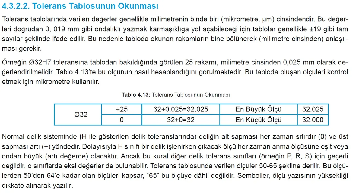
Values in ISO tolerance tables are in micrometres (µm); divide by 1000 for millimetres. If the table gives +25 / 0 for Ø32 H7, that is +0,025 / 0 mm: maximum size 32,025, minimum 32,000. For H holes the lower deviation is always zero, so the hole can never be smaller than its basic size. Tables are arranged in size ranges (e.g. 30–50 mm) and the upper limit belongs to the range.

The ISO system: letters and numbers
ISO 286 describes a tolerance with a letter and a number, for example H7 or g6.
- The letter gives the position of the tolerance zone relative to the zero line. Capital letters (A…ZC) are holes; lower case (a…zc) are shafts.
- The number gives the width of the zone — the IT grade. IT01 is the tightest, IT18 the widest. The smaller the number, the tighter the tolerance.
Two rules worth memorizing. For H the lower deviation is always zero — an H hole is never smaller than its basic size. For h the upper deviation is always zero — an h shaft is never larger than its basic size. Everything else in the system is built around those two.
So Ø20 H7 means a hole 20,000 to 20,021 mm. Ø20 h6 means a shaft 19,987 to 20,000 mm. Same nominal size, opposite direction of tolerance.
The three types of fit
| Fit | Condition | Typical pairs | Used for |
|---|---|---|---|
| Clearance | shaft always smaller than hole | H7/g6, H7/f7, H8/e8 | sliding and rotating parts, guides |
| Transition | may be either, depending on actual sizes | H7/k6, H7/j6, H7/n6 | accurate location, parts that must be dismantled |
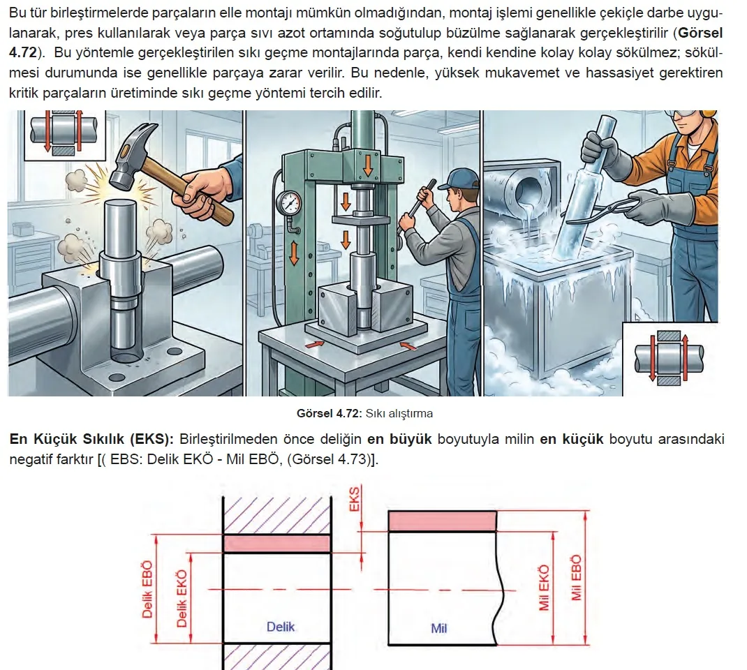
| Interference | shaft always larger than hole | H7/p6, H7/s6, H7/u6 | permanently joined parts, bushes, gear hubs |
On a tolerance diagram the rule is easy to see: if the hole zone lies entirely above the shaft zone the fit is a clearance fit; entirely below, an interference fit; if they overlap, a transition fit.
Which fit is used where: fit character tables
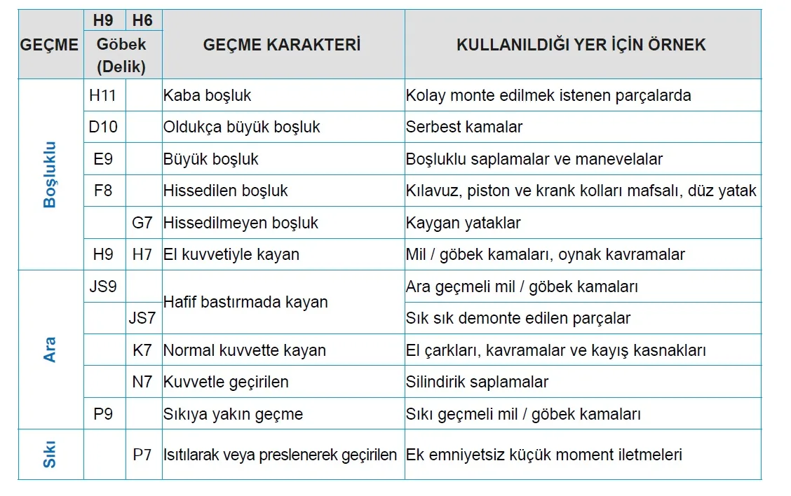
Knowing that H7/g6 means a “just perceptible clearance” used for precision sliding bearings tells you what the part does. The two tables below summarise, for the hole basis system (H7 and H8 holes; H9 and H6 holes), the fit character given by the common shaft classes and where each is typically used. The tables are in Turkish; the column order is: fit type – hole – shaft – character – typical use.

Hole basis and shaft basis
- Hole basis. The hole is kept at H and the shaft letter is changed to obtain the fit: H7/g6, H7/k6, H7/p6.
- Shaft basis. The shaft is kept at h and the hole letter is changed: G7/h6, K7/h6, P7/h6.
Both give identical fits. In practice the hole basis system is preferred, because a hole is made with a fixed-size tool — a drill, a reamer, a broach — while a shaft can be turned to any size. Changing the shaft is cheap; changing the hole means a new tool.
Shaft basis is used where a single long shaft or a standard drawn bar has to carry several different fits along its length — for example a transmission shaft with a bearing, a gear and a pulley on it.
How a fit is written on a drawing
- On an assembly drawing: Ø20 H7/g6 — hole tolerance first, shaft tolerance second.
- On a detail drawing: only that part’s own tolerance, e.g. Ø20 H7 or Ø20 g6.
- Deviations may also be written directly as figures, e.g. 20 +0,0210.
- Dimensions with no tolerance are covered by the general tolerance note, usually ISO 2768-m.
Worked Example: Ø30 H7/g6 Tolerance Zones
Let us put real numbers on a fit. For Ø30, an H7 hole gets +21/0 µm and a g6 shaft −7/−20 µm. The hole zone sits above the zero line and the shaft zone just below it, so this is a clearance fit: at tightest 7 µm and at loosest 41 µm of clearance — the shaft always enters the hole, never jams:
Second example: Ø25 H7/h6 step by step
H7/h6 is the clearance fit at the “slides when lubricated” limit. For Ø25 the values are read from the 18–30 mm range: H7 hole +21/0 µm, h6 shaft 0/−13 µm. Hole 25,000–25,021, shaft 24,987–25,000. Minimum clearance 0 (smallest hole, largest shaft), maximum clearance 0,034 mm.

Test yourself
- What does the capital letter in H7 tell you?
That it is a hole, and where its tolerance zone sits relative to the basic size. - What does the 7 in H7 tell you?
The IT grade — the width of the tolerance zone. Smaller number, tighter tolerance. - What is the lower deviation of any H hole?
Zero. - Ø30 H7/p6 — what kind of fit is that?
An interference fit; the shaft is always larger than the hole. - Why is hole basis preferred?
Because holes are made with fixed-size tools; it is far cheaper to vary the shaft. - A shaft measures 19,992 mm and is specified Ø20 h6 (19,987–20,000). Accept or reject?
Accept — it is inside the zone. - What governs a dimension with no tolerance written on it?
The general tolerance standard named in the title block, typically ISO 2768-m.
Next lesson. Size tolerance controls how big a feature is. It says nothing about whether a face is flat, an axis straight or two bores concentric. Lesson 9 covers geometrical tolerancing — the 14 symbols, the tolerance frame and datums.
Technical Drawing Training — all lessons
- Lesson 1: Introduction, Paper Sizes, Title Block and Scale
- Lesson 2: Line Types, Line Widths and Lettering
- Lesson 3: Geometric Constructions, Tangency, Polygons and the Ellipse
- Lesson 4: Orthographic Projection, Views and First vs Third Angle
- Lesson 5: Section Views, Hatching Rules and Parts Never Hatched
- Lesson 6: Dimensioning Rules, Systems and Tolerance Accumulation
- Lesson 7: Surface Texture, Ra and Surface Symbols
- Lesson 8: Dimensional Tolerances and the ISO System of Fits ← you are here
- Lesson 9: Geometrical Tolerances — The 14 Symbols, Frame and Datums
- Lesson 10: Pictorial Projection, Isometric Drawing and Sketching
- Lesson 11: Assembly Drawings, Detail Drawings and the Parts List
- Lesson 12: Reading a Drawing for the CNC Operator
- Technical Drawing Symbols and Abbreviations Glossary
- Welding Symbols on Technical Drawings (ISO 2553)