
A drawing without dimensions is a picture. Dimensioning is what turns it into a manufacturing document. And unlike shape, dimensioning has consequences: where you take a dimension from decides how accurately the part can actually be made.
The four elements
- Dimension line — continuous thin, with an arrowhead at each end, drawn parallel to the feature being dimensioned.
- Extension line — continuous thin, projected from the part, leaving a small gap at the part and running 2–3 mm past the dimension line.
- Arrowhead — 15° included angle, length about ten times the line width, filled.
- Dimension figure — placed above the middle of the dimension line, with a small gap, never touched or crossed by any line.
General rules
- All dimensions are in millimeters and the unit is not written. If another unit is used it is stated in a note.
- A feature is dimensioned once. Repeating a dimension in a second view invites contradiction.
- Dimensions are placed outside the outline wherever possible.
- Smaller dimensions go closest to the part, larger ones further out — so that extension lines do not cross dimension lines.
- Dimension lines must never cross each other, and never coincide with an outline or a center line.
- Figures are written so they can be read from the bottom and from the right of the sheet.
- Dimension the feature in the view where it appears most clearly — usually where its true shape is shown.
Dimensioning cylindrical (turned) parts
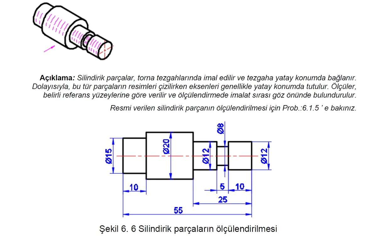
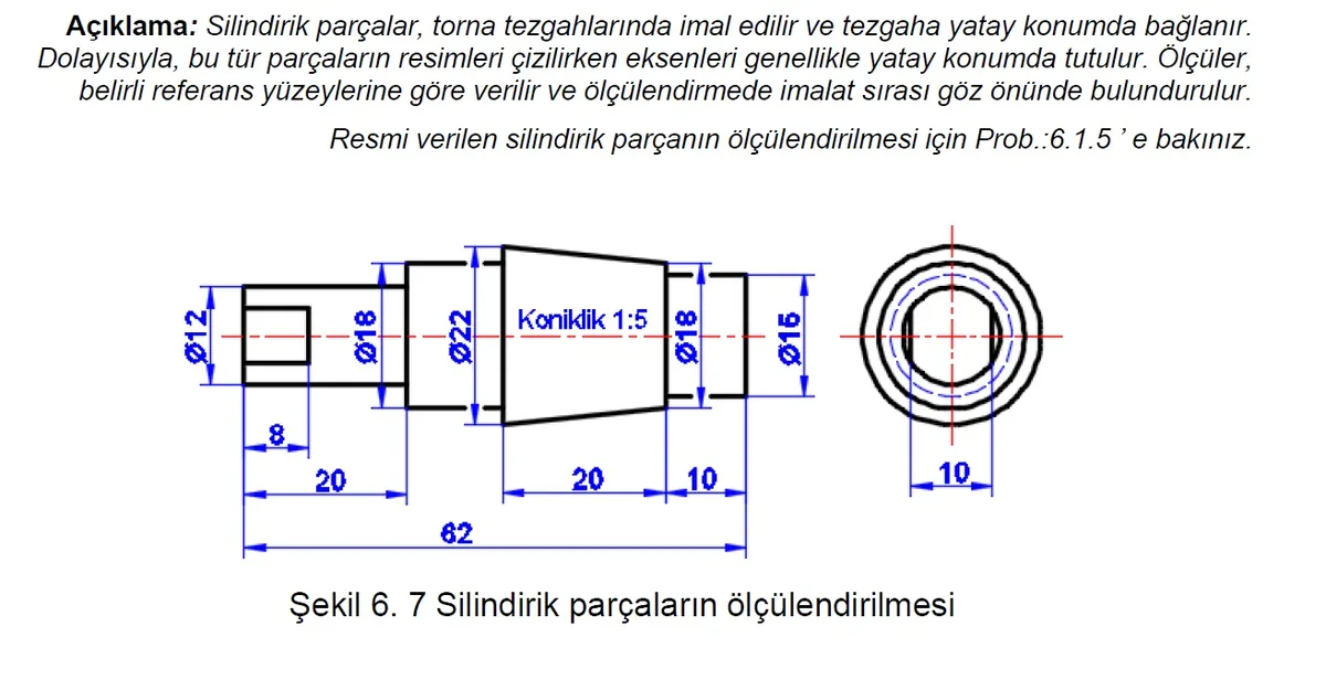
Shafts, bushes and pins are held horizontally in the lathe, so they are drawn with the axis horizontal and every diameter is written with the Ø symbol on a single view. Lengths are given from the end face that will be the reference on the machine, so the operator never has to add or subtract dimensions. A taper is written as a ratio (1:5) or an angle, a sphere as SØ, a chamfer as 1×45°.
The three dimensioning systems
- Parallel (datum) dimensioning. Every dimension is taken from one common face. Errors do not accumulate. This is the default choice for anything that must be accurate.
- Chain dimensioning. Each dimension starts where the last one ended. Convenient, but tolerances add up.
- Running dimensioning. A space-saving form of parallel dimensioning: one origin marked with a circle, single arrowheads, figures written at the extension lines.
Tolerance accumulation. Three chain dimensions of 40 ±0,1 give a total of 120, but the deviation at the far end is ±0,3 — three times as much. Dimension the same part from one datum and the last face is still within ±0,1. This is why chain dimensioning is avoided wherever accuracy matters.
Why tolerances accumulate in chain dimensioning
In a chain, each dimension starts where the previous one ended. If the first one is off by 0,1 mm, the second starts from that displaced point, and so does the third. The last feature ends up displaced by the sum of all the errors.
| System | Reference | Error behaviour | When to use it |
|---|---|---|---|
| Parallel | One common datum | Errors do not accumulate | Parts needing accurate location |
| Running | One origin, single arrowheads | No accumulation, saves space | Crowded drawings with many dimensions |
| Chain | Each from the previous | Tolerances add up | When the spacing between features matters more than their position |
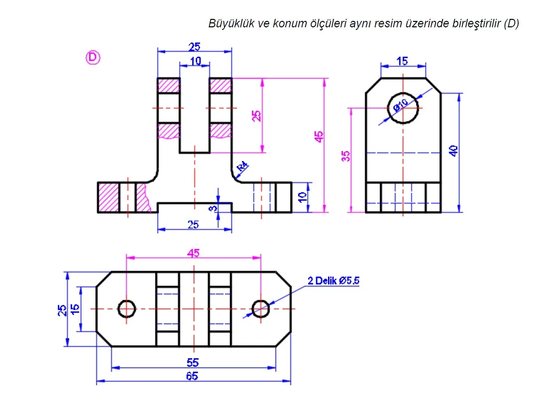
Whichever system is used, dimensions fall into two kinds: size dimensions that define a feature (hole diameter, slot width, thickness) and location dimensions that say where it is (distance of a hole center from the edges). A good drawing gives both for every feature, and combines them in the same view.
Dimensioning specific features
| Feature | Symbol | Rule |
|---|---|---|
| Circle / cylinder | Ø | Always give the diameter, never the radius. Ø40, not R20. |
| Arc / fillet | R | Give the radius. The arrow points outward from the center. |
| Sphere | SØ or SR | S in front of Ø or R. |
| Square | □ | □25 means a 25 × 25 square section. |
| Chamfer at 45° | — | Written on one line: 2×45°. |
| Chamfer not at 45° | — | Depth and angle dimensioned separately. |
| Repeated features | × | 4×Ø12 means four holes, all Ø12, dimensioned once. |
| Auxiliary dimension | ( ) | In brackets, for information only — not to be worked to. |
| Not to scale | underlined | An underlined figure is correct even though the drawing is not. |
Choosing the datum
The datum is not chosen at random. It should be:
- a functional surface — one that actually locates the part in the assembly;
- a surface that can be reached and measured;
- ideally the same surface the part will be located on during manufacture.
When the design datum and the manufacturing datum are the same face, tolerances are easiest to hold. When they differ, the tolerance has to be shared between the two — and the part gets harder to make than the drawing suggests.
Worked Example: Dimensioning a Plate with a Hole
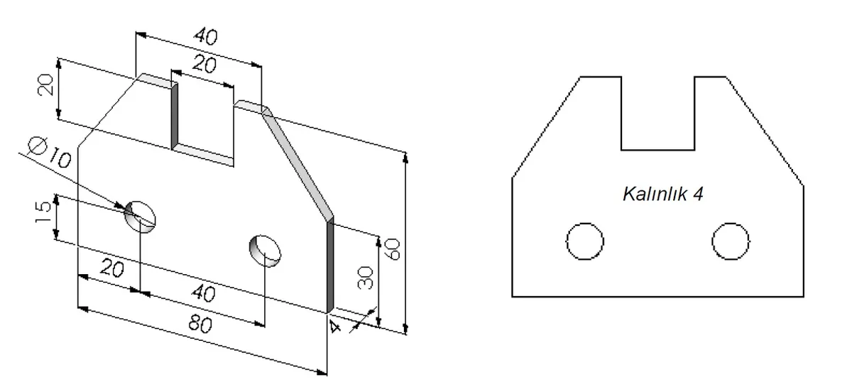
All four elements on one part: a 100×60 plate with a Ø20 hole. The bottom-left corner is chosen as the datum; the hole’s position is dimensioned from the two edges, and the diameter is taken outside with a leader line. Note: dimension figures sit above the line, never through it; extension lines start with a small gap from the part:
Test yourself
- A drawing shows “40” with no unit. What is it?
40 millimeters. Millimeters are the default and are not written. - Why should the same dimension not appear in two views?
If one is later changed the two contradict each other, and the part becomes ambiguous. - A hole is 20 mm across. How is it dimensioned?
Ø20 — diameter, not R10. - What does 4×Ø9 mean?
Four holes, each Ø9, dimensioned once for all four. - What does a dimension in brackets mean?
It is an auxiliary dimension, given for information only; it is not manufactured to and carries no tolerance. - Three chain dimensions of 30 ±0,1 — what is the deviation at the end?
±0,3. Chain tolerances add. - Why is an underlined dimension figure underlined?
The drawing is not to scale at that point; the written figure is the correct one.
Next lesson. Dimensions say how big. Lesson 7 covers surface texture — how smooth each surface has to be, what Ra means, and how the surface symbol is built up.
Technical Drawing Training — all lessons
- Lesson 1: Introduction, Paper Sizes, Title Block and Scale
- Lesson 2: Line Types, Line Widths and Lettering
- Lesson 3: Geometric Constructions, Tangency, Polygons and the Ellipse
- Lesson 4: Orthographic Projection, Views and First vs Third Angle
- Lesson 5: Section Views, Hatching Rules and Parts Never Hatched
- Lesson 6: Dimensioning Rules, Systems and Tolerance Accumulation ← you are here
- Lesson 7: Surface Texture, Ra and Surface Symbols
- Lesson 8: Dimensional Tolerances and the ISO System of Fits
- Lesson 9: Geometrical Tolerances — The 14 Symbols, Frame and Datums
- Lesson 10: Pictorial Projection, Isometric Drawing and Sketching
- Lesson 11: Assembly Drawings, Detail Drawings and the Parts List
- Lesson 12: Reading a Drawing for the CNC Operator
- Technical Drawing Symbols and Abbreviations Glossary
- Welding Symbols on Technical Drawings (ISO 2553)