
G71 is a multiple repetitive roughing cycle that, on FANUC-controlled CNC lathes, removes excess material from an outside or inside diameter by automatically distributing the cutting passes according to a defined finished part profile. Instead of programming every roughing pass individually, the operator defines the depth of cut, the tool retract amount, the start and end lines of the profile, the finishing allowances in X and Z, and the roughing feed. The CNC then calculates the region between the stock and the finished profile and generates the roughing tool paths itself.
However, G71 does not behave the same way across all FANUC generations. The cycle format, Type II behaviour, pocket count, profile checking, tool-nose radius compensation and the meaning of some parameters can differ between the old FANUC Series 0/00/0-Mate, FANUC 0i-C, FANUC 21i-TB, and FANUC 0i-D / 0i Mate-D. For this reason a G71 program should not be copied directly from another machine; the exact control model and the program format in use must be identified first.
📷 IMAGE AREA — G71 roughing cycle: stock boundary, finished profile and pass distribution diagram
Suggested alt text: G71 rough turning cycle pass distribution diagram
1. What operations is G71 used for?
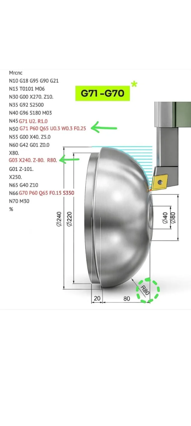
G71 is mainly used to remove roughing stock along the Z axis. The most common applications are:
- Outside-diameter rough turning
- Inside-diameter rough turning (boring)
- Stepped shafts
- Tapered surfaces and radiused transitions
- Parts with several diameters and diameters that change along the profile
- Pocketed profiles, if the control and option support it
- Rough machining of cast or forged material
In G71 the main roughing direction is generally parallel to the Z axis. For facing-direction roughing, where the main pass is parallel to the X axis, G72 is used instead.
2. How G71 works
Rather than memorising G71 as a code template, it is important to understand what the CNC actually calculates. The control unit uses: the start point where the cycle is called, the boundary of the raw stock, the finished profile marked by P and Q, the amount of stock to remove on each pass, the retract after each pass, the X and Z finishing allowances, and whether the profile geometry is Type I or Type II.
The CNC then applies approximately the following sequence:
- Moves from the start point to the first roughing level.
- Cuts the part in the Z direction.
- Retracts when it reaches the profile boundary and returns safely to the start of the next pass.
- Steps one pass deeper in the X direction.
- Repeats until the whole profile is roughed out.
- Leaves the finishing allowances given by U and W on the profile.
- If required, the same profile is finish-turned later with
G70.
G71 is therefore a stock-removal cycle that automatically divides the area between a defined profile and the raw stock into layers.
3. The classic two-line G71 format
On FANUC 0i-C, 21i-TB and many other FANUC lathe applications the common format is:
G71 U(Δd) R(e);
G71 P(ns) Q(nf) U(Δu) W(Δw) F(f) S(s) T(t);

Example:
G71 U2.0 R0.5;
G71 P100 Q180 U0.4 W0.2 F0.25;| Address | Meaning |
|---|---|
| U on the first line | Radial depth of cut Δd |
| R on the first line | Retract amount e after each roughing pass |
| P | Sequence number where the profile starts |
| Q | Sequence number where the profile ends |
| U on the second line | Finishing allowance left in X |
| W | Finishing allowance left in Z |
| F | Roughing feed used during G71 |
| S | Spindle speed / cutting speed used for G71 |
| T | Tool command for G71; its use depends on the machine |
There are two different U values here and they must not be confused: U on the first G71 line is the depth of cut, while U on the second G71 line is the X finishing allowance. The FANUC manual likewise explains that the meaning of the same address is determined by whether P and Q are present.
3.1 U on the first line: depth of cut
In G71 U2.0 R0.5; the U2.0 is the depth of cut applied on each roughing step. Whether this is a diameter or radius value depends on the control unit and the machine builder settings. Many FANUC lathes work in diameter programming, but the G71 depth of cut is interpreted as a radial value in some formats. In particular, in the Series 10/11 compatibility format whether parameter No.1004 bit 7 IPR applies to the G71/G72 depth of cut can be set on the 0i-C with parameter No.5103 bit CID. For this reason the question “is U2.0 2 mm on diameter or 2 mm on radius?” must not be answered definitively without seeing the machine model.
The safest practice is: check the machine builder parameter list, try a small sample program in graphics or machine-lock mode, run the first attempt at a low override, and verify the tool path with no tool or part clamped.
3.2 R on the first line: retract amount
R sets how far the tool moves away from the cut surface at the end of each roughing pass. In G71 U2.0 R0.5; the tool makes an approximately 0.5 mm safety retract after each pass. If R is too small the tool may rub the surface on return, chips may pack against the insert, the cutting edge may wear, and a return witness mark may form. If R is too large the cycle time increases, the tool travels unnecessarily, collision risk rises in small bores, and unexpected transition paths can appear in pocketed profiles. On old Series 0/00/0-Mate systems the retract amount can be given by R in the program and is also related to the corresponding parameter value; in the old manual the G71/G72 depth of cut and retract values are shown in the 0717–0718 parameter group.
3.3 P and Q: profile boundaries
In G71 P100 Q180 ...; P100 indicates the profile starts at line N100 and Q180 that it ends at line N180. Example profile:
N100 G00 X40.0;
N110 G01 Z0.0;
N120 X42.0 Z-2.0;
N130 Z-20.0;
N140 X50.0;
N150 Z-40.0;
N160 X60.0 Z-50.0;
N180 Z-70.0;
The CNC treats the geometric moves between N100 and N180 as the finished part profile. Between the P and Q lines there should generally be only the G00, G01, G02, G03 moves needed to form the profile. The 21i manual explicitly states that M98, M99, unsuitable one-shot G codes and non-profile G codes cannot be used between P and Q. The same manual reports that if the first block marked by P does not contain G00 or G01, alarm P/S 065 occurs.
3.4 U on the second line: X finishing allowance
In G71 P100 Q180 U0.4 W0.2 F0.25; the U0.4 is the finishing allowance left in X. On a diameter-programmed lathe U0.4 usually means 0.4 mm on the diameter, so the radial surface allowance is 0.2 mm. This interpretation must be confirmed against the control format, the diameter/radius programming setting, and the machine builder configuration. On an outside diameter a positive U usually leaves material on the outside; on inside-diameter work the sign direction can be reversed. A wrong sign can cause the tool to cut into the finish dimension with the roughing pass.
3.5 W: Z finishing allowance
W is the finishing allowance left in the Z direction. For example, W0.2 aims to leave 0.2 mm of axial allowance on the face and shoulder regions of the profile. However, the sign must be chosen carefully according to profile direction: is the part zero at the right face, is the cut going in Z-, is an inside or outside diameter being machined, is there a reverse-direction face at the end of the profile? A wrong W sign can spoil the shoulder dimension, drive the tool into the profile, and cause unexpected motion in the G70 finishing cycle.
3.6 The effect of F, S and T
The F, S and T values given in the G71 call block or before the cycle are the ones used during the roughing cycle. The F, S and T commands inside the P–Q profile blocks may be ineffective during G71 roughing. The FANUC 0i-C manual states that instead of the F, S and T values written between the profile blocks, the values defined in the G71 block or the preceding block are effective; the same applies to G96/G97 changes written inside the profile. The following structure is therefore safer:
G96 S180 M03;
G50 S2500;
G00 X66.0 Z2.0;
G71 U2.0 R0.5;
G71 P100 Q180 U0.4 W0.2 F0.25;
4. What is G71 Type I?
Type I is the classic and more limited G71 profile type. In Type I the profile must generally advance in one direction, be monotonic in the roughing direction, contain no pockets or reversing diameter moves, and not turn back on itself in the cutting direction. In simple terms, as the tool follows the profile from start to end the X values must always change in the same direction. In outside-diameter turning the following structure suits Type I:
N100 G00 X30.0;
N110 G01 Z0.0;
N120 X36.0 Z-3.0;
N130 Z-20.0;
N140 X44.0;
N150 Z-40.0;
N160 X52.0 Z-48.0;
N180 Z-65.0;
The profile diameters grow in one direction: 30 → 36 → 44 → 52.
4.1 How Type I is selected
In the classic FANUC format the distinction is made by the axis addresses in the first profile block marked by P. For Type I only an X-axis move is given on the P line (e.g. N100 G00 X30.0;) or, incrementally, N100 G00 U-20.0;. No Z move appears in the first block. The rule in the old FANUC manual is clear: if a single axis is specified in the first profile block it is Type I; if two axes are specified it is Type II.
4.2 The main limitation of Type I
In a Type I profile there must be no reversal in the X direction. For example a profile of X40.0 → X50.0 → X46.0 → X60.0 is not valid for Type I because the X value first increases and then decreases. Depending on the control unit and parameter setting it may raise an alarm, treat the profile as invalid, or — if profile checking is off — generate a risky tool path. If the profile really is pocketed, Type II must be used; if it is not actually pocketed, the program geometry must be corrected.
📷 IMAGE AREA — Comparison of Type I (monotonic profile) and Type II (pocketed / reversing profile)
Suggested alt text: G71 Type I versus Type II profile comparison
5. What is G71 Type II?
Type II is the advanced G71 type that can machine reversing profiles and pockets. In Type II the profile does not have to grow or shrink continuously in the X direction. For example, in the diameter sequence 40 → 50 → 44 → 56 → 48 → 62 there are two separate reversals and therefore pocket-like regions. According to the FANUC 0i-C manual, in Type II the profile need not be monotonic along the X axis, and up to 10 concave pockets can be defined on this generation.
5.1 How Type II is selected
For Type II both X and Z addresses appear in the first profile block. Even if no real Z move is needed, W0 is written explicitly: N100 G00 X30.0 W0; or N100 G00 X30.0 Z0.0;. The example distinction in the old manual is:
(TYPE I)
G71 U10.0 R5.0;
G71 P100 Q200 ... ;
N100 X... ;

(TYPE II)
G71 U10.0 R5.0;
G71 P100 Q200 ... ;
N100 X... W0;
If Type II is intended but there is no Z move in the first block, omitting W0 can cause the control to perceive the cycle as Type I.
5.2 Is Type II available on every machine?
No. Type II can be optional on some old controls. The old FANUC manual states that the multiple repetitive cycle addition option is required for Type II. Therefore, the program form being accepted, the G71 code being recognised, and the Type II profile actually being machinable are not the same thing. If the option is not present on the machine, the Type II format may raise an alarm or be unsupported.
6.1 Insert and tool-holder selection for Type II plunging
Activating Type II in software is not enough on its own; the tool that will physically perform the plunging motion must have suitable geometry. Standard 80° CNMG inserts offer no plunge freedom. For Type II pocket-clearing work, 55° DNMG or 35° VNMG inserts should be selected together with neutral/negative approach-angle holders (PDJNR/L for DNMG, SVJCR/L for VNMG).
The basic rule: the plunge angle of the profile (α) must be at least 3°–5° smaller than the clearance (relief) angle of the tool (β). Otherwise the holder body rubs against the side wall; chatter, surface degradation and insert breakage are inevitable. On critical profiles, verify by simulation that the plunge angle stays within the tool’s clearance limits before cutting.
6. Differences between Type I and Type II
| Feature | Type I | Type II |
|---|---|---|
| Profile structure | One-way, monotonic | Can be pocketed / reversing |
| P line | Only X/U | X/U together with Z/W |
| If no Z move | Z/W not written | W0 must be written |
| Pocket machining | Not suitable | Suitable |
| Geometry check | Monotonicity matters | Separate rules per generation |
| Option requirement | Usually the basic cycle | Option may be required on old models |
| Programming risk | Lower | Tool path must be examined more carefully |
7. Important G71 differences between FANUC control generations
The same G71 code can behave differently on different FANUC generations. The differences below are the points that cause the most trouble when moving a program that runs on one machine to another.
Difference 1 — Series 0/00/0-Mate parameter numbers differ from newer models
In the old Series 0/00/0-Mate parameter manual the G71/G72 settings include 0393#1 MCQ (Q sequence-number check), 0393#4 (whether the pocket shape is treated as valid/invalid) and 0717–0718 (depth of cut and retract). These numbers are not the same as parameters such as 5102, 5103, 5104, 5132 used on the 0i-C and 0i-D. Conclusion: a parameter number found on old FANUC must not be applied directly to a 0i-C or 0i-D.
Difference 2 — On the 0i-C the G71/G72 depth of cut is parameter No.5132
In the FANUC 0i-C parameter manual, parameter 5132 sets the default depth of cut for the G71 and G72 multiple repetitive cycles. In the two-line G71 format, if the depth of cut is written with U in the program the program value is used; in different program formats or applications where the value is omitted, the parameter takes over.
Difference 3 — On the 0i-D, 5132 is defined as a real number
In the 0i-D parameter manual, parameter 5132 is again the G71/G72 depth of cut, but its data type is defined as a real-number path value. For example, in the IS-B system the valid range is given as 0.0 to +999999.999. In the corresponding 0i-C manual version, 5132 is shown as two-word data; so even though the same number exists, the on-screen display and data-entry format can differ by generation.
Difference 4 — 0i-C parameter 5102 MRC
5102#1 MRC determines whether an alarm is raised when a non-monotonic shape is defined in a Type I G71/G72 profile. If MRC=0 no alarm occurs; if MRC=1 alarm P/S 064 occurs. This bit applies only to Type I. Important safety note: setting MRC=0 does not make a wrong profile correct — it only suppresses the alarm. If the profile is really Type II, the solution is to define Type II correctly with N100 G00 X... W0; and verify the tool path.
Difference 5 — 0i-C parameter 5102 QSR
5102#2 QSR determines whether the sequence number given at Q is checked to exist in the program before the G70–G73 cycle starts. If QSR=0 no pre-check is done; if QSR=1 the Q line is searched beforehand and, if not found, the cycle is not started and an alarm occurs. This bit helps prevent the tool from going to an unexpected part of the profile because of a wrong Q number.
Difference 6 — 0i-C parameter 5102 RFC
5102#4 RFC determines whether tool-nose radius compensation is applied on the G71/G72 semi-finish shape or the G73 cutting pattern. RFC=0 not applied, RFC=1 applied. Used incorrectly, the profile dimension can change, the tool path can shift at tight corners, and unexpected motion can occur at pocket bottoms. This parameter should not be trusted without the tool-nose direction number and nose radius entered correctly.
Difference 7 — RFC behaviour changed on the 0i-D
Whereas on the 0i-C tool-nose radius compensation for G71–G73 can be partly selected with 5102#4 RFC, on the 0i-D the same RFC bit is not used; tool-nose radius compensation is incorporated into the control behaviour for the G70–G73 cycles. For this reason the advice “set 5102#4 to 1” prepared for the 0i-C cannot be applied directly to the 0i-D.
Difference 8 — 0i-C parameter 5103 P15
If the Series 10/11 command format is used, 5103#2 P15 sets the Type II G71/G72 pocket machining order. P15=0 uses the FS0/FS16 order, P15=1 the FS10/11 order. This choice affects whether the pockets are traversed pass by pass or whether one pocket is completed before moving to the next.
Difference 9 — P15 is not used on the 0i-D
On the 0i-D 5103#2 P15 does not exist. While the 0i-C can advance per pocket or per pass according to the standard format, the 0i-D completes clearing one pocket and then moves to the next. In the 0i-C standard format there is a 10-pocket limit for Type II; 11 or more pockets can cause alarm P/S 068. On the 0i-D the pocket count is not limited in this way.
Difference 10 — 0i-C parameter 5103 COD
5103#3 COD sets the axis order for the return to the start point at the end of pocket clearing. COD=0 means X first then Z; COD=1 means Z first then X. FANUC notes that COD=1 can prevent the tool from interfering with the workpiece surface, especially on facing-type returns. This parameter should not be read as “set to 1 on every machine”; return safety must be checked according to the tool holder, workpiece, inside/outside diameter and approach direction.
Difference 11 — Parameter 5104 FCK
5104#2 FCK checks the relationship between the programmed profile and the cycle start point before G71/G72 begins. If FCK=0 no pre-check is done; if FCK=1 the profile is checked and, if the relationship is wrong, alarm P/S 062 occurs. Example of a wrong condition: a positive finishing allowance is used but the start point is smaller than the profile maximum, or a negative allowance is used but the start point is larger than the profile minimum. The check is performed on the programmed profile before the cycle starts; return and escape paths are outside its scope.
Difference 12 — 0i-D parameters 5145 and 5146
The 0i-D offers two tolerance parameters for the very small geometric deviations coming from CAM software. 5145 sets the permitted value for very small monotonicity violations in the roughing direction in G71/G72 (e.g. when a profile that theoretically goes continuously in Z- produces a small Z+0.001 reversal in the CAM output). 5146 sets the permitted value for small monotonicity violations in the cutting direction in Type I. These values are entered as radius values. Critical warning: 5145 and 5146 must not be used to machine a real pocket with Type I, to hide a large programming error, or to force a wrong profile direction to be accepted; they are only for tolerating micron-level deviations produced by the CAM system.
Difference 13 — 0i-D parameters 5105 RF1 and RF2
On the 0i-D, 5105#1 RF1 and 5105#2 RF2 control whether roughing is performed again after the return to the start point. RF1 is for Type I, RF2 for Type II. General meaning: 0 means roughing is performed, 1 means it is not. Because these settings change the repeat-motion behaviour of the cycle, only the value recommended by the machine builder should be used.
Difference 14 — 0i-D parameter 5106 GFX
On systems with the grinding-cycle option, 5106#0 GFX can change the meaning of the G71–G74 codes. If GFX=0, G71–G74 are lathe multiple repetitive cycle commands; if GFX=1, G71–G74 are grinding canned-cycle commands. When this parameter is changed the power must be turned off and on again. It is one of the special cases to check when “I wrote the G71 code but the lathe cycle I expected does not run”.
8. Summary of G71 parameters
Main G71/G72 parameters for FANUC 0i-C
| Parameter | Bit/value | Function |
|---|---|---|
| 5102 | MRC | P/S 064 alarm control for non-monotonic Type I profile |
| 5102 | QSR | Checks the Q sequence number before the cycle |
| 5102 | RFC | Tool-nose radius compensation on G71/G72 semi-finish profile |
| 5103 | P15 | Type II pocket machining order in FS10/11 format |
| 5103 | COD | X/Z order on return to the start point |
| 5103 | CID | Applying the IPR setting to depth of cut in FS10/11 format |
| 5104 | FCK | Profile / start-point consistency check |
| 5132 | Numeric | G71/G72 depth of cut |
Main G71/G72 parameters for FANUC 0i-D
| Parameter | Bit/value | Function |
|---|---|---|
| 5104 | FCK | Pre-cycle profile check |
| 5105 | RF1 | Type I post-return roughing behaviour |
| 5105 | RF2 | Type II post-return roughing behaviour |
| 5106 | GFX | Whether G71–G74 are lathe or grinding cycles |
| 5132 | Real number | G71/G72 depth of cut |
| 5145 | Real number | Permitted deviation 1 for monotonicity |
| 5146 | Real number | Permitted deviation 2 in the Type I cutting direction |
Corresponding settings for old Series 0/00/0-Mate
| Parameter | Function |
|---|---|
| 0393#1 | Q sequence-number check |
| 0393#4 | Pocket shape / geometry check |
| 0717–0718 | G71/G72 depth of cut and retract |
These tables do not mean that the same parameters exist on every machine. The control software version and the machine builder options must always be verified.
9. Complete G71 outside-diameter example
The following example is written to teach the two-line FANUC format:
%
O7101
(G71 OD ROUGH TURNING)
G21
G18
G40
G99
G50 S2500
T0101
G96 S180 M03
M08
G00 X66.0 Z2.0
G71 U2.0 R0.5
G71 P100 Q180 U0.4 W0.2 F0.25
N100 G00 X30.0
N110 G01 Z0.0
N120 X34.0 Z-2.0
N130 Z-15.0
N140 X42.0
N150 Z-35.0
N160 X52.0 Z-45.0
N170 Z-60.0
N180 X60.0
G00 X100.0 Z100.0
T0202
G96 S220
G00 X66.0 Z2.0
G70 P100 Q180
G00 X150.0 Z150.0
M09
M05
M30
%
9.1 Explanation of the program
G21metric input,G18the X-Z plane,G40tool-nose radius compensation cancel,G99feed per revolution.G50 S2500limits the maximum spindle speed to 2500 rpm while using constant surface speed.G96 S180 M03starts 180 m/min constant surface speed and clockwise spindle rotation.G00 X66.0 Z2.0brings the tool to the cycle start point, which must be outside the raw diameter, in front of the face, and safe for the retract moves.G71 U2.0 R0.5depth of cut and retract;G71 P100 Q180 U0.4 W0.2 F0.25profile boundaries, finishing allowances and roughing feed.G70 P100 Q180finish-turns the same profile.
10.1 G71 for internal (boring) work and the sign logic
G71 is the primary roughing method not only for external turning but also for enlarging pre-drilled bores. The direction and sign management is the exact opposite of external work: the boring bar starts from the small pre-drilled diameter and enlarges the bore in layers toward the wall, and since the finishing tool will clean the inner wall, roughing must leave the bore undersized relative to the final profile. For this geometric reason the X finishing allowance on the second line must be negative for internal work (e.g. U-0.4). If entered positive, the control offsets the passes outside the final size and the tool has no room to move inside the bore (see 13.1).
The cycle start point must be radially smaller than the pre-drilled diameter with a safe clearance (e.g. below X45 for a Ø45 pre-bore). On internal work the R retraction of the first line moves toward the bore center (X0 direction); if the start point is chosen too close to the wall, the tool plunges into the material during retraction.
10.2 Internal Type II example program
The example below machines a pocketed (non-monotonic) internal profile inside a Ø100 mm pre-drilled part. Writing X and Z together in block N80 activates Type II; U-0.4 is the internal finishing allowance.
%
O1002 (G71 TYPE 2 INTERNAL PLUNGE CYCLE) ;
N10 G21 G40 G80 G99 ;
N20 G50 S1800 ;
N30 T0303 M06 (T03: Boring Bar - DNMG 110404, Left Hand) ;
N40 G96 S140 M03 (Cutting Speed: 140 m/min) ;
N50 G00 X45.0 Z3.0 M08 (Start Point Set Smaller Than Pre-Bore O45) ;
(--- G71 Cycle Start ---)
N60 G71 U1.5 R0.5 ;
(U1.5: 1.5mm Depth of Cut on Radius) ;
(R0.5: 0.5mm Safety Clearance Retraction Toward Center) ;
N70 G71 P80 Q140 U-0.4 W0.1 F0.18 ;
(U-0.4: NEGATIVE SIGN FOR INTERNAL FINISH ALLOWANCE) ;
N80 G00 X80.0 Z3.0 (TYPE 2 ACTIVATION: BOTH X AND Z IN SAME BLOCK) ;
N90 G01 Z0.0 F0.12 ;
N100 X70.0 Z-15.0 (Plunging Inward - Monotonicity Broken) ;
N110 Z-35.0 (Pocket Bottom) ;
N120 G03 X90.0 Z-45.0 R10.0 (Concave Radius Transition) ;
N130 G01 Z-60.0 ;
N140 X42.0 (Profile End - Retract Toward Center) ;
(--- G71 Cycle End ---)
N150 G00 Z10.0 M09 ;
N160 G28 U0. W0. M05 ;
N170 M01 ;
(--- FINISHING OPERATION ---)
N180 T0404 M06 (T04: Internal Finish Boring Bar) ;
N190 G96 S200 M03 ;
N200 G00 X45.0 Z3.0 M08 ;
N210 G41 (Tool Nose Radius Compensation - Left Active) ;
N220 G70 P80 Q140 ;
N230 G40 G00 Z20.0 M09 ;
N240 G28 U0. W0. M05 ;
N250 M30 ;
%
10. Type II example
The structure below should only be used on a control that supports Type II:
G00 X72.0 Z2.0
G71 U2.0 R0.5
G71 P100 Q200 U0.5 W0.2 F0.22
N100 G00 X34.0 W0
N110 G01 Z0.0
N120 X40.0 Z-3.0
N130 Z-15.0
N140 X52.0
N150 Z-28.0
N160 X44.0
N170 Z-38.0
N180 X58.0
N190 Z-55.0
N200 X64.0
The W0 in N100 G00 X34.0 W0 makes the cycle recognised as Type II. In the profile there is a change X40 → X52 → X44 → X58; the X value first increases, then decreases, then increases again. The profile is therefore not Type I.
11. Why is the tool start point so important in G71?
The tool position before G71 is called is used by the CNC to calculate the roughing area. A wrong start point can lead to alarm P/S 062 or PS0322, the first pass plunging into the raw stock in rapid, the tool hitting the face, rubbing the part surface on the return, the finishing allowance being left on the wrong side, or, in boring, the tool coming out of the bore.
When setting the start point: the X value must be outside the raw diameter, the Z value in front of the face; it must be verified that the tool holder will not hit the part; room must be left for the R retract; the return path of Type II pockets must be examined; and the turret, chuck and tailstock limits must be considered.
📷 IMAGE AREA — G71 cycle start point, raw diameter boundary and safe approach distance
Suggested alt text: G71 cycle start point and safety clearance
12. G71 alarm solutions
Alarm numbers can appear in different forms depending on the control generation, such as P/S 064, PS0064 or PS0329.
P/S 062 — Profile and start point inconsistent
Causes: the start X value does not clear the profile; despite a positive finishing allowance the start point is smaller than the profile maximum; despite a negative allowance the start point is larger than the profile minimum; the inside/outside diameter direction is set wrong; 5104#2 FCK=1 so the pre-check catches the error. Solution: check the X-Z start point before G71, find the maximum/minimum X of the profile, verify the signs of the U and W allowances; remember that directions on an inside diameter differ from an outside diameter. Correct the geometry rather than turning FCK off.
P/S 064 (PS0064) — Non-monotonic profile
Causes: a Type I profile reverses in X; the profile has a pocket but Type I was selected; W0 was forgotten on the P line; the CAM program produced a very small reverse move such as 0.001 mm; 5102#1 MRC=1 on the 0i-C; the 0i-D monotonicity check detected a real deviation. Solution: examine the profile line by line, order the X values; if there is a real pocket use Type II and ensure the first P block has both X and Z/W; if the deviation is only CAM rounding, 5145/5146 can be considered on the 0i-D. Do not hide a large geometric error with a parameter.
P/S 065 — No G00 or G01 in the P block
The first profile line marked by P does not explicitly state G00 or G01. Instead of the faulty N100 X30.0;, write N100 G00 X30.0; or N100 G01 X30.0;. The 21i manual states that alarm P/S 065 occurs in this case.
P/S 066 — Profile program error
On some generations this is related to a wrong P/Q order, a forbidden command in the P/Q range, the profile not being defined properly, or the Q line coming before P. Checklist: does the P number really exist? Does the Q number exist? Is P before Q? Is the same N number used twice? Is there an M98/M99 or another cycle call between P and Q? Is the last profile line complete?
P/S 067 — G71 called in MDI mode
G70, G71, G72 and G73 cannot be run in MDI mode on many old FANUC controls. The 21i manual states that P/S 067 occurs if a G70–G73 command is issued in MDI mode. Solution: store the program in memory, edit it in EDIT mode and run it in MEMORY/AUTO mode.
P/S 068 — Too many pockets
The 0i-C Type II standard format supports at most 10 pockets; 11 or more can cause P/S 068 (this limit is removed on the 0i-D). Solution: split the profile into two separate G71 cycles, clear some regions with normal G00/G01; if the control really is a 0i-D, verify the program format and the selected compatibility mode.
PS0322 — Finish shape exceeds the start point
In the 0i-D alarm list this is explained as the G71/G72 profile exceeding the cycle start point. Solution: move the start X value to a safer outside diameter, move the start Z value in front of the face, check all maximum/minimum points of the profile; on an inside diameter make sure the start diameter is on the correct side.
PS0323 — First profile block has an unexpected Type II command
On the 0i-D, a Z/W in the first profile block for G71 (or an X/U for G72) can under certain conditions cause Type II detection and an alarm. Solution: if Type I is intended, remove the Z/W address from the G71 P line; if Type II is intended, verify the control Type II support and the program format; check whether an old 0i-C program is being run in the 0i-D compatibility format.
PS0324 — Interruption-type macro call during the cycle
An interruption-type custom macro was called while G70–G73 was running. Solution: disable the interruption-type macro call during the G71 range; check the PMC or machine builder macro; if the cause is not visible in the user program, contact the machine builder.
PS0325 — Unusable command in the profile program
There is an unsupported command in the P–Q range. Things to check: M98/M99, other cycle codes, unsuitable one-shot G codes, plane change, coordinate-system change, tool change in the middle of the profile, macro calls and direct-dimension commands.
PS0326 — Last profile block in the middle of a direct-dimension command
On the 0i-D the last block of the profile program marked by Q cannot end in the middle of a chamfer, corner radius or direct drawing-dimension input command. Solution: include the next block that completes the chamfer or radius command within the Q boundary as well.
13.1 Two common shop-floor accidents (no alarm, scrapped parts)
Accident 1 — Entering a positive U finishing allowance on internal work: After the first pass the boring bar hits the bore wall at G00 rapid while exiting; the bar snaps, turret misalignment may occur and the part is scrapped. The root cause is a positive U value in an internal cycle: the control offsets the allowance toward the larger diameter and pushes the passes outside the material boundary. Solution: the X finishing allowance in internal G71 code must always be negative (e.g. U-0.4). Note that this mistake produces no alarm — the path is valid to the control; the accident happens physically.
Accident 2 — Holder body rubbing during Type II plunging: Severe chatter and screeching during the plunge, insert corners chip instantly, the spindle load meter peaks and tearing/burn marks form on the back wall of the pocket. The root cause is geometry, not software: the holder’s clearance angle is smaller than the profile’s plunge angle, so the body rubs on the material. Solution: apply the tool-selection rules in 6.1 (DNMG/VNMG inserts + PDJNR/SVJCR holders) and verify the α < β − 3°–5° condition by simulation.
13. What to check when G71 runs but the tool path is wrong
The absence of an alarm does not mean the program is safe. Check the following items in order:
- Control model: which one — Series 0-TC/0-TD, 0i-TC/0i-TD, 0i Mate-TC/TD, 21i-TB/21i-TA?
- Program format: FANUC 0 standard, Series 10/11 compatibility, old single-line or new two-line format.
- Diameter/radius programming: are X addresses diameter or radius?
- Interpretation of the pass value: the diameter/radius behaviour of U on the first line or of 5132.
- Type I/Type II selection: the axis addresses on the P line.
- Tool-nose compensation: nose radius, imaginary tool-nose direction, G41/G42, RFC or generation behaviour.
- Start point: is the tool on the correct side of the profile and the raw stock?
- Sign of the finishing allowances: do not memorise the same sign for outside and inside diameters.
- Return order: especially 5103 COD on the 0i-C.
- Grinding-cycle selection: if 5106#0 GFX is wrong on the 0i-D the meaning of G71 can change.
14. How to change a FANUC parameter
Before changing a parameter the current values must be backed up. FANUC manuals clearly state that CNC and PMC parameters are set at the factory and normally should not be changed. A wrong parameter setting can cause the machine to move unexpectedly, damage tools or the machine, and cause injury. The procedure below is the general FANUC procedure; the steps may differ because of machine-builder screens, a key lock, PMC protection or a password system.
14.1 Before making a change
- Take a full backup of the parameters and record the old value of the parameter to be changed in writing.
- Verify the control model; determine whether the parameter is a bit or numeric parameter and whether it requires a power off/on.
- Put the machine in a safe condition, stop the spindle, end the automatic cycle, and enable emergency stop if possible.
- Only authorised technical personnel should change the parameter.
14.2 Changing a parameter on the FANUC 0i-C
Put the control in MDI mode or emergency stop; open the SETTING screen with OFFSET/SETTING; move the cursor to the PARAMETER WRITE line; enable parameter writing with [(OPRT)] and [ON:1] (or type 1 and INPUT). The P/S100 PARAMETER WRITE ENABLE alarm that appears is normal. From the SYSTEM/PARAM screen find the parameter number, record the old value, enter the new value and press INPUT. When done, return to the SETTING screen, set PARAMETER WRITE back to 0, and clear the P/S100 alarm with RESET. If P/S000 PLEASE TURN OFF POWER appears, turn the CNC power off and on according to procedure.
14.3 Changing a parameter on the FANUC 0i-D
On the 0i-D the process is largely the same: switch to MDI mode or enable emergency stop, set PARAMETER WRITE to 1 on the SETTING screen (the SW0100 PARAMETER WRITE ENABLE alarm appears), go to the parameter on the PARAMETER screen, record the old value and enter the new value with INPUT, set PARAMETER WRITE back to 0 and clear the SW0100 alarm with RESET. If there is a power-off note, turn the CNC off and on. On the 0i-D, parameter-write permission is related to No.8900#0 PWE within the system.
14.4 Changing a parameter on the old Series 0/00/0-Mate
Switch to MDI mode, press DGNOS/PARAM and open the PARAM screen, go to the parameter number, set PWE to 1 (P/S100 appears), enter the new value and press INPUT, set PWE back to 0 and clear the alarm with RESET. If alarm 000 appears, turn the power off and on again.
15. The big mistake when changing a bit parameter
For example, if 5102 = 00010110 and only the MRC bit is to be changed, the whole value must not be rewritten at random. The bit order on screen is usually #7 #6 #5 #4 #3 #2 #1 #0 and only the relevant bit should be changed. Accidentally changing the other bits can alter the behaviour of other cycles, sequence-number checking, tool-nose compensation, drilling cycles and the machine builder special functions. For example, besides MRC, 5102 also contains other G71-related bits such as QSR and RFC; that is why a photo or record of all eight bits should be taken first.
16. Safe testing after a parameter change
Do not go straight to production after changing a parameter. Test sequence: turn parameter writing off, clear the alarm, power the CNC off/on if required, perform the reference return, check the tool offsets and the workpiece zero. Run the program on the graphics screen, examine the tool path with machine lock if available, and dry-run with no tool or part clamped. Turn on single-block mode, set the rapid and feed overrides to the lowest safe level, make the first real cut in a test material, measure the stock removed on the first pass and observe the return/retract paths. If the result is wrong, restore the parameter to its old value.
17. The expert operator approach to G71
G71 expertise is not merely memorising the two-line format. An expert operator must also understand the exact FANUC generation of the control, the command format in use, the Type I/Type II distinction, the monotonicity of the profile, the pocket-count limit, the tool retract order, the diameter/radius interpretation of the X axis, the sign direction of the finishing allowances, tool-nose radius compensation, the G71–G70 relationship, and the effect of the start point.
The most important principle of expertise is this: when a G71 alarm occurs, the first solution is not to change a parameter. First check the program format, profile geometry, Type I/Type II selection, start point and the finishing-allowance signs. A parameter should only be considered after the control model has been verified and the real function of the parameter is fully understood.