
G72 is a multiple repetitive roughing cycle that, on FANUC-controlled CNC lathes, removes the excess material on the face side of the part by automatically distributing the passes along a defined finished profile. G71 and G72 are very similar, but their main stock-removal directions differ: G71 roughing moves are mostly parallel to the Z axis, while G72 roughing moves are mostly parallel to the X axis. In other words, G71 clears the part lengthwise, whereas G72 works inward layer by layer starting from the face.
G72 is especially useful on flanges, disc-shaped parts, pulleys, wide face surfaces, parts with several steps on the face side, large-diameter but short parts, conical or radiused profiles on the face, and (if the control and option support it) pocketed face profiles. However, G72 does not behave the same way across all FANUC generations (Series 0/00/0-Mate, 0-TD, 0i-C, 21i-TB, 0i-D and 0i Mate-D); there can be differences in profile checking, Type I/Type II detection, tool-nose radius compensation, pocket machining order and the data types of the parameters.
1. The basic working principle of G72

The G72 cycle divides the material between the face side of the raw part and the programmed finished profile into layers. The control unit uses: the cycle start point, the depth of each face pass, the retract after each pass, the start and end lines of the profile, the X and Z finishing allowances, the roughing feed, and whether the profile is Type I or Type II.
The CNC performs approximately these steps: it moves from the tool start point to the first Z pass level, makes a facing cut along X, retracts when it reaches the profile boundary and returns safely to the start-diameter side, advances to the next pass level in Z, and repeats until the whole face profile is roughed out; it leaves the X and Z finishing allowances, and if required the same profile is finished later with G70. The FANUC manual states that G72 uses the same basic logic as G71, but the cutting move is made parallel to the X axis.
2. When is G72 preferred over G71?
If the excess material of the part is distributed mainly along the face rather than along the diameter, G72 may be more suitable. For example, if the raw part is close to the finished size in diameter but has 15–30 mm of excess material on the face, has several face steps, and is a short, wide flange, the G72 cycle is more logical. While G71 clears a long cylindrical stock lengthwise in Z, G72 divides a wide, thick face stock into layers along Z and cuts each layer along X.
3. The classic two-line G72 format
The common FANUC format is:
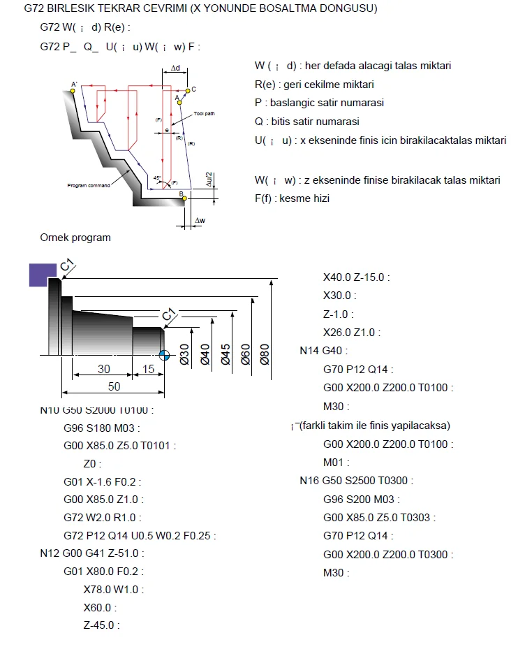
G72 W(Δd) R(e);
G72 P(ns) Q(nf) U(Δu) W(Δw) F(f) S(s) T(t);

Example:
G72 W2.0 R0.5;
G72 P100 Q180 U0.4 W0.2 F0.22;| Address | Function |
|---|---|
| W on the first line | Z-direction depth of each roughing face pass |
| R on the first line | Retract amount after each cut |
| P | Profile start sequence number |
| Q | Profile end sequence number |
| U on the second line | Finishing allowance in X |
| W on the second line | Finishing allowance in Z |
| F | G72 roughing feed |
| S | Spindle speed / cutting speed for the cycle |
| T | Tool command; its use depends on the machine builder |
4. W on the first line: roughing depth of cut
In G72 W2.0 R0.5; the W2.0 sets how far the tool advances in the Z direction on each roughing face pass. For example, if the start is Z2.0, the finished face profile about Z-10.0, and the depth W2.0, the control may create facing cuts at approximately Z0, Z-2, Z-4, Z-6, Z-8, Z-10. The real tool path varies with the profile shape, the finishing allowance and the control algorithm.
Critical point: the W on the first G72 line does not mean the same as the W on the second line. The first-line W2.0 is the roughing depth of cut; the second-line W0.2 is the finishing allowance left in Z. Confusing these two W values is one of the most common mistakes in G72 programs.
5. R on the first line: retract amount
In G72 W2.0 R0.5; the R0.5 sets how far the tool moves away from the cut surface after completing the facing cut along X. General motion: the tool cuts along X, retracts when it reaches the profile boundary, returns in rapid to the next start point, and advances to the new pass level in Z. If R is too small the edge may rub the surface on return, chips may pack, a line may form on the face, and edge wear may increase. If R is too large the cycle time grows, idle motion increases and collision risk arises in inside-face work. In the 0i-D parameter manual the G71 and G72 retract value is associated with parameter 5133, and it is stated that this value must always be entered as a radius value.
6. P and Q: the start and end of the face profile
In G72 P100 Q180 ...; P100 indicates the profile starts at line N100 and Q180 that it ends at line N180. Example face profile:
N100 G00 Z0.0;
N110 G01 X60.0;
N120 Z-4.0 X56.0;
N130 X48.0;
N140 Z-8.0;
N150 X36.0;
N160 Z-14.0;
N180 X20.0;
The control treats the moves between N100 and N180 as the finished face profile. Between P and Q there should generally be the G00, G01, G02, G03 moves that form the profile; depending on the generation, chamfer, corner radius and direct drawing-dimension input may be supported or limited. Between P and Q, M98 subprogram calls, M99, another roughing cycle, forbidden one-shot G codes, tool changes, commands that change the coordinate system, and interruption-type macro calls must not be used. The 21i manual clearly states that M98 and M99 cannot be used between P and Q in the G70–G73 cycles.
7. U on the second line: X finishing allowance
In G72 P100 Q180 U0.4 W0.2 F0.22; the U0.4 is the finishing allowance left in X. On a diameter-programmed control U0.4 usually means 0.4 mm on the diameter, so the radial surface allowance is 0.2 mm. However, whether the control programs in diameter or radius, whether the operation is from the outside toward the center, whether an inside-face profile is being machined, and whether the U sign leaves material on the correct side of the profile must all be verified. A wrong U sign can cause the roughing tool to exceed the finish dimension, leave no material for the G70 finishing cycle, or drive the tool into the surface in an inside profile.
8. W on the second line: Z finishing allowance
In G72 P100 Q180 U0.4 W0.2 F0.22; the W0.2 is the finishing allowance left in Z on the finished face profile. In G72 this value is especially important, because the roughing depth of cut is also defined along the Z axis. When determining the sign, check whether Z-plus is out of the chuck, whether the part zero is on the face, whether roughing advances in Z-, whether the profile is on the front or back face, and whether an outside face or an inside pocket bottom is being machined. FANUC manuals show four cutting patterns for G72 according to the U and W signs; the cutting moves are parallel to the X axis, but the direction of the cycle depends on the U/W signs.
9. The behavior of F, S and T within the cycle
The F, S and T values defined in the G72 call block or before the cycle are the ones effective during roughing. The F, S and T values written inside the P–Q profile blocks are, in most FANUC applications, not used during G72 roughing. For example, when roughing with G72 P100 Q180 U0.4 W0.2 F0.25, an N120 G01 X60.0 F0.12; inside the profile is effective only later, in the G70 finishing cycle. In the FANUC 0i-TC example the roughing feed F0.3 is used in the G72 block and F0.15 for finishing inside the profile, after which the same profile is finished with G70.
10. What is G72 Type I?
Type I is the classic G72 form used for monotonic face profiles without pockets. The profile must generally change in one direction in Z, not turn back on itself, contain no pocketed/recessed face structure, and be monotonic in the roughing direction. A simple Type I face profile:
N100 G00 Z0.0;
N110 G01 X70.0;
N120 Z-4.0 X64.0;
N130 X54.0;
N140 Z-8.0;
N150 X42.0;
N160 Z-14.0;
N180 X24.0;
The Z values advance in one direction: 0 → -4 → -8 → -14.
11. How G72 Type I is selected
In G72 the first profile block marked by P contains only a Z-axis move: N100 G00 Z0.0; or, incrementally, N100 G00 W-2.0;. The first profile block of Type I must not contain an X or U move. In the old FANUC alarm descriptions, a Z/W in the P block of G71 or an X/U in the P block of G72 can be treated as an unsuitable Type II or an invalid first block. The FANUC manual requires the A–A approach path in G72 to be defined with G00 or G01 in the P block, and in the classic Type I form there must be no X-axis move in this first block.
12. What is G72 Type II?
Type II is used for more complex geometries with reversals or pockets in the face profile. For example, if the Z values change as 0 → -5 → -2 → -9 → -6 → -14, the profile turns back on itself in Z and is not suitable for Type I. In Type II the profile can reverse in Z, contain face pockets, and form nested steps. However, Type II does not mean a completely free profile; especially on the 0i-D the monotonicity conditions in the roughing direction are checked.
13. How G72 Type II is selected
In G72 Type II both Z/W and X/U addresses must appear in the first profile block. Even if no real X move is made, U0 is written explicitly: N100 G00 Z0.0 U0; or N100 G00 Z0.0 X80.0;. While G71 Type II usually uses W0, its counterpart in G72 Type II is U0. That is: G71 Type II has X and Z/W in the first block (W0 if there is no Z move); G72 Type II has Z and X/U in the first block (U0 if there is no X move). This distinction is critically important.
14. G72 Type I versus Type II comparison
| Feature | G72 Type I | G72 Type II |
|---|---|---|
| Profile structure | Monotonic face profile without pockets | Pocketed or reversing face profile |
| First P block | Only Z/W move | Z/W together with X/U |
| If no X move | X/U not written | U0 is written |
| Pocket machining | Not suitable | Suitable |
| Profile check | Monotonicity required | Checked differently per generation |
| Option on old systems | Usually the basic cycle | Type II option may be required |
| Programming risk | Lower | Return paths must be examined carefully |
15. How is profile monotonicity evaluated in G72?
In G72 the main roughing move is along X, but the pass advance direction is the Z axis. There are therefore two monotonicity concerns: the roughing pass direction (Z axis) and the cutting direction (X axis). In Type I, unsuitable reversals in both the roughing pass direction and the cutting direction of the profile can raise an alarm. In Type II a pocket structure is allowed, but the profile must obey the roughing rules the control accepts. On the 0i-D a monotonicity violation on the first plane axis can raise PS0064 and a violation on the second plane axis PS0329; parameters 5145 and 5146 can grant tolerance only for small CAM deviations.
16. Why is the G72 start point so important?
The X and Z position of the tool before G72 is called determines the roughing area of the cycle. The start point must be outside the raw material, in front of the face, safe for the turret and tool holder, suitable for the retract move, and on the correct side of the finishing allowances. For example, if starting with G00 X170.0 Z5.0, X170.0 must be outside the profile and the raw diameter, and Z5.0 must provide a safe distance in front of the face. If the start point is wrong, the first move may plunge into the part in rapid, the tool may hit the face, alarm PS0322 or P/S062 may appear, and the finishing allowance may be left on the wrong side. On the 0i-C, parameter 5104#2 FCK checks the relationship between the profile and the cycle start point; if the relationship is wrong, P/S062 occurs.
17. The four basic direction combinations for G72
FANUC manuals show four cutting patterns for G72 according to the U and W signs: U(+) W(+), U(+) W(-), U(-) W(+), U(-) W(-). These allow the cycle to be adapted from outside to center, center to outside, from the front face to the back, or to a reverse-direction face profile. However, these signs should not be memorized; they must be evaluated according to the coordinate system of the part being programmed. To determine the signs, mark the start point and the start point of the finished profile, find whether the X move is plus or minus, determine the Z-direction roughing advance, ensure the finishing allowance stays outside the part, and verify the tool path in graphics.
18. G72 outside-face Type I example
%
O7201
(G72 FACE ROUGH TURNING TYPE I)
G21
G18
G40
G99
G50 S2200
T0101
G96 S170 M03
M08
G00 X166.0 Z4.0
G72 W2.0 R0.5
G72 P100 Q180 U0.4 W0.2 F0.25
N100 G00 Z0.0
N110 G01 X140.0
N120 X120.0 Z-3.0
N130 Z-6.0
N140 X90.0
N150 Z-10.0
N160 X60.0 Z-14.0
N170 Z-18.0
N180 X30.0
G00 X190.0 Z50.0
T0202
G96 S210
G00 X166.0 Z4.0
G70 P100 Q180
G00 X200.0 Z100.0
M09
M05
M30
%
19. Line-by-line explanation of the Type I example
G21metric input,G18X-Z plane,G40tool-nose radius compensation cancel,G99feed per revolution.G50 S2200limits the maximum spindle speed while using constant surface speed;G96 S170 M03170 m/min constant surface speed.G00 X166.0 Z4.0the cycle start point.G72 W2.0 R0.5pass 2 mm, retract 0.5 mm;G72 P100 Q180 U0.4 W0.2 F0.25profile N100–N180, X allowance 0.4, Z allowance 0.2, roughing feed 0.25 mm/rev.N100 G00 Z0.0the first profile block of G72 Type I — only a Z move.G70 P100 Q180cleans the finishing allowances left by G72 over the same profile.
20. The G72 example from the FANUC manual
N010 G50 X220.0 Z190.0;
N011 G00 X176.0 Z132.0;
N012 G72 W7.0 R1.0;
N013 G72 P014 Q019 U4.0 W2.0 F0.3 S550;
N014 G00 Z58.0 S700;
N015 G01 X120.0 W12.0 F0.15;
N016 W10.0;
N017 X80.0 W10.0;
N018 W20.0;
N019 X36.0 W22.0;
N020 G70 P014 Q019;
In this example the roughing depth of cut is 7 mm, the retract 1 mm, the X finishing allowance 4 mm, the Z finishing allowance 2 mm, the roughing feed 0.3 mm/rev and the finishing feed inside the profile 0.15 mm/rev.
21. G72 Type II example
The following example is for training on a control that supports Type II:
%
O7202
(G72 FACE ROUGH TURNING TYPE II)
G21
G18
G40
G99
G50 S2000
T0101
G96 S160 M03
M08
G00 X170.0 Z4.0
G72 W2.0 R0.5
G72 P100 Q200 U0.4 W0.2 F0.22
N100 G00 Z0.0 U0
N110 G01 X140.0
N120 Z-5.0 X125.0
N130 X100.0
N140 Z-2.0
N150 X82.0
N160 Z-9.0
N170 X60.0
N180 Z-6.0
N190 X42.0
N200 Z-14.0 X24.0
G00 X200.0 Z80.0
M09
M05
M30
%
The critical line is N100 G00 Z0.0 U0: the first block contains both the Z address and the U address representing the X axis; U0 is used because no real X move is made. In the profile the Z values reverse as 0 → -5 → -2 → -9 → -6 → -14, so the profile is Type II, not Type I.
22. The relationship between G72 and G70
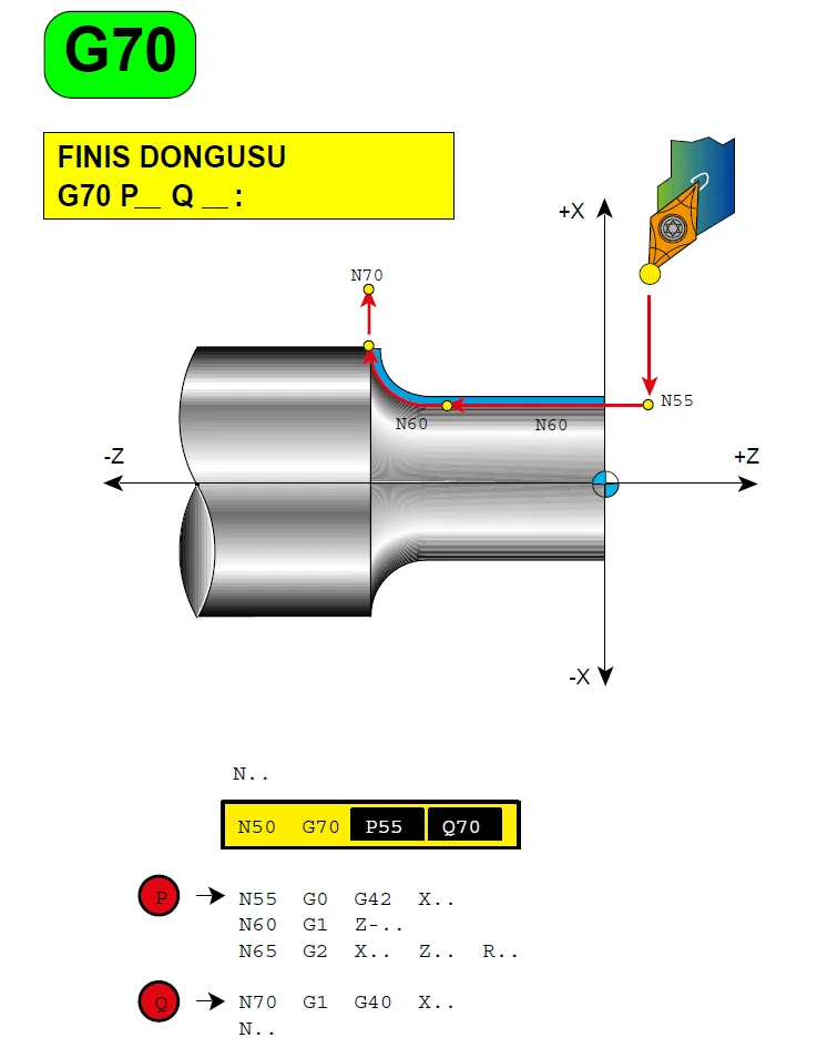
G72 removes the roughing stock; G70 then finishes the same profile defined between P and Q. When G70 runs, the X and Z finishing allowances left by G72 are cleaned, the appropriate F and S values in the profile blocks can be used, and the tool returns to the start point and moves on to the next block. The FANUC manual explains that after roughing with G71, G72 and G73, the same P–Q profile can be finished with G70.
23. Main parameters related to G72
Many G72 parameters are shared with G71, because the two cycles are in the same multiple repetitive cycle family.
23.1 Parameter 5132 — G71/G72 depth of cut
On the FANUC 0i-C, parameter 5132 sets the depth of cut for the G71 and G72 multiple repetitive roughing cycles. On the 0i-D, 5132 is a real-number path parameter (in the IS-B system the example range is 0.0 to +999999.999). In the two-line standard G72 form, if G72 W2.0 R0.5; is written the program W2.0 explicitly defines the depth of cut; in different program formats or applications where the value is omitted, parameter 5132 takes over.
23.2 Parameter 5133 — G71/G72 retract amount
On the 0i-D, parameter 5133 sets the retract amount of the G71 and G72 cycles. The manual states the value must be entered in mm or inch, as a positive real number, and always using a radius value. The relationship between the program R command and the parameter must be evaluated according to the control format.
23.3 Parameter 5134 — approach clearance up to the start of cutting
On the 0i-D, parameter 5134 sets the safety clearance up to the point where cutting feed begins in the G71/G72 cycles. This value affects the transition from rapid approach to cutting feed and the approach distance to the part; 5134 is also entered as a radius value.
23.4 Parameter 5102 bit MRC
On the 0i-C, 5102#1 MRC determines whether an alarm is raised when a non-monotonic shape is detected in a G71 or G72 Type I profile. If MRC=0 no P/S064 is raised; if MRC=1 P/S064 is raised for a non-monotonic Type I profile. On the 0i-D this bit does not exist and the monotonicity check is enforced by the system. Important: setting MRC to zero does not make a wrong G72 profile correct; if the profile really is pocketed, Type II must be selected, the first profile block written correctly, and the tool path verified.
23.5 Parameter 5102 bit QSR
5102#2 QSR affects whether the sequence number given at Q is checked to exist in the program before the P–Q cycle starts. On the 0i-D the existence of the Q line is checked regardless of the QSR setting, and if not found PS0063 can occur.
23.6 Parameter 5102 bit RFC
On the 0i-C, 5102#4 RFC determines whether tool-nose radius compensation is applied on the G71 or G72 semi-finish shape (RFC=0 not applied, RFC=1 applied). On the 0i-D this bit is removed; tool-nose radius compensation is incorporated into the control behavior for the G70–G73 cycles.
23.7 Parameter 5103 bit P15
On 0i-C systems using the Series 10/11 program format, 5103#2 P15 can set the G71/G72 Type II pocket machining order. If P15=0 the tool can move from one pocket to another on each pass; if P15=1 one pocket is completed before moving to the next. On the 0i-D P15 is not used; the control completes one pocket before moving to the next.
23.8 Parameter 5103 bit COD
On the 0i-C, COD affects the axis order on the return to the start point in the G71/G72 cycles (X first then Z, or Z first then X). Because G72 works near the face surface, the return order can be critical; a wrong return order can cause the tool to rub the face, hit a step, or the tool holder to touch inside a face pocket. COD should not be set to the same value on every machine; the tool direction and the machine builder setting must be the basis.
23.9 Parameter 5104 bit FCK
5104#2 FCK checks the G71/G72 profile before the cycle starts. If FCK=0 no pre-check is done; if FCK=1 the profile and start point are checked, and if the relationship is wrong P/S062 (or the relevant profile alarm on newer systems) can occur. Checked conditions include the start point being smaller than the profile maximum despite a positive allowance, or larger than the minimum despite a negative allowance. The check is on the programmed profile; retract and return paths are outside its scope.
23.10 Parameter 5104 bit MCC
On the 0i-C, MCC affects whether an unsuitable arc command inside the G71/G72 profile is checked before motion starts. The manual states that MCC is effective when MRC=1 and that the geometry of the arc command is also checked during motion.
23.11 Parameters 5105 RF1 and RF2
On the 0i-D, 5105#1 RF1 and 5105#2 RF2 determine whether roughing is performed again after the return to the start point. RF1 is for G71/G72 Type I, RF2 for Type II; 0 means roughing is performed, 1 means it is not. If the roughing allowance is defined separately in the Series 10/11 format, the effect of these bits can change.
23.12 Parameter 5145 — monotonicity tolerance 1
On the 0i-D, 5145 allows very small monotonicity violations in the roughing pass direction during G71/G72; for G72 this generally relates to very small reverse moves in Z. For example, if the CAM output produces Z-5.000, Z-4.999, Z-8.000, the 0.001 mm reverse deviation may be a rounding error rather than a real pocket; entering a suitable small tolerance in 5145 lets the cycle run without an alarm. However, a real pocket or a large geometric error must not be hidden with 5145.
23.13 Parameter 5146 — monotonicity tolerance 2
5146 allows small monotonicity violations in the cutting direction in Type I. Since the cutting direction in G72 is the X axis, it can be evaluated for very small unsuitable reversals produced by CAM in the X direction. FANUC states the tolerance is entered unsigned, as a radius value, and can be limited by the depth of cut.
23.14 Parameter 5106 GFX
On 0i-D systems with the grinding option, 5106#0 GFX can determine whether the G71–G74 codes are lathe or grinding cycles. If GFX=0 they are lathe multiple repetitive cycles; if GFX=1 they can be interpreted as grinding cycles. When this parameter is changed a power off/on may be required.
24. Summary of G72 parameters
FANUC 0i-C
| Parameter | Bit/value | Relation to G72 |
|---|---|---|
| 5102 | MRC | Alarm control for non-monotonic Type I profile |
| 5102 | QSR | Q sequence-number check |
| 5102 | RFC | Tool-nose radius compensation on the semi-finish profile |
| 5103 | P15 | Type II pocket machining order in Series 10/11 format |
| 5103 | COD | Axis order on return to the start point |
| 5104 | FCK | Profile / start-point pre-check |
| 5104 | MCC | Unsuitable arc command check |
| 5132 | Numeric | G71/G72 depth of cut |
FANUC 0i-D
| Parameter | Bit/value | Relation to G72 |
|---|---|---|
| 5104 | FCK | Profile start-point check |
| 5105 | RF1 | Type I post-return roughing |
| 5105 | RF2 | Type II post-return roughing |
| 5106 | GFX | G71–G74 lathe/grinding meaning selection |
| 5132 | Real number | G71/G72 depth of cut |
| 5133 | Real number | G71/G72 retract |
| 5134 | Real number | Approach clearance up to the start of cutting |
| 5145 | Real number | Small monotonicity deviation in the roughing pass direction |
| 5146 | Real number | Small monotonicity deviation in the Type I cutting direction |
25. G72 differences between 0i-C and 0i-D
Difference 1 — Monotonicity check
On the 0i-C the Type I monotonicity check can depend on the 5102#1 MRC setting. On the 0i-D the MRC bit does not exist and the check is continuous: a first-axis violation gives PS0064, a second-axis violation PS0329. Parameters 5145 and 5146 can be used for small CAM deviations.
Difference 2 — Type II monotonicity check
On the 0i-C MRC is not effective in a Type II profile and some monotonicity checks may not be applied. On the 0i-D the appropriate monotonicity conditions are also checked in Type II; small deviations are acceptable only within the 5145 tolerance.
Difference 3 — Pocket machining order
In the 0i-C standard format the tool can move between pockets on each pass. On the 0i-D the tool completes clearing one pocket and then moves to the next.
Difference 4 — Pocket count limit
On the 0i-C up to 10 pockets can be supported for Type II; 11 or more can cause PS0068. On the 0i-D the pocket count is not limited in this way. Because the phrase “10 or more pockets” can appear in the old Series 0/00/0-Mate manuals, the software version and manual edition must be checked.
Difference 5 — Tool-nose radius compensation
On the 0i-C a partial behavior can be selected for G71/G72 with 5102#4 RFC. On the 0i-D the RFC bit does not exist; tool-nose radius compensation is incorporated into the system behavior for the G70–G73 cycles.
Difference 6 — Chamfer and corner R
On the 0i-C there can be more restrictions on chamfer, corner R and direct dimensioning in the profile program. On the 0i-D these commands can be used, but the last block marked by Q cannot end in the middle of a chamfer or corner-radius command; otherwise PS0326 occurs.
P/S041 — Interference / overcut in tool-nose radius compensation
Symptom and cause: G41 or G42 tool-nose radius compensation was activated inside the roughing lines. During the roughing passes the compensation vector becomes impossible to calculate at narrow corners of the profile; the tool may collide with tight corners on the face or remove excess stock (overcut), and the control raises the P/S041 alarm.
Solution: Do not use radius compensation during roughing. Activate G41/G42 only right before the block where the finishing tool is called and the G70 cycle is run, and cancel it with G40 at the end of the cycle. Compensation behavior inside the cycle also varies by control generation (see Difference 5 and PS0328).
26. G72 alarm solutions
P/S061 — P or Q address missing
P or Q was not written in the G72 call. Instead of the faulty G72 P100 U0.4 W0.2 F0.25;, write G72 P100 Q180 U0.4 W0.2 F0.25;. Alarm lists state that 061 is given when P or Q is missing in the G70–G73 commands.
P/S062 — G72 depth of cut is zero or negative
G72 W0 R0.5; or G72 W-2.0 R0.5; was written. FANUC gives a zero or negative G71/G72 depth of cut as a cause of 062. Solution: use a positive pass value (e.g. G72 W2.0 R0.5;). The cutting direction is determined by the cycle geometry and profile position, not by the W sign.
P/S062 — Start point / profile inconsistency
When FCK is active, 062 can also arise from the start-point/profile relationship. Check: is the start Z in front of the profile, does the start X clear the profile, are the U and W allowances the correct sign, do the profile max/min values exceed the start point, and are the directions correct in inside-face work. The profile and start point should be corrected rather than turning the parameter off.
P/S063 — P sequence number not found
The sequence number written at P does not exist in the program (e.g. G72 P100 ... but no N100). Check whether N100 really exists, whether a leading zero was used, whether the same number is used elsewhere, and whether the P and Q numbers are correct.
P/S064 (PS0064) — Profile is not monotonic
Causes: a reversal in Z in a Type I profile; using Type I when G72 Type II is required; forgetting U0 in the P block; an unsuitable reversal in X; the CAM system producing a very small reverse move; MRC=1 on the 0i-C; the 0i-D monotonicity check catching the error. Solution: write the Z values of the profile in order, use Type II if there is a real pocket, use the X/U and Z/W addresses correctly in the first P block, write U0 if there is no X move; consider 5145/5146 only if there is a micron-level CAM deviation. Do not hide a real geometric error with a parameter.
PS0329 — Monotonicity error on the second axis
On the 0i-D, PS0329 occurs when the monotonic increase/decrease condition on the second plane axis of the profile is not met. Solution: plot the profile blocks graphically, tabulate the X and Z values separately, determine whether the reverse move is a real pocket or a CAM rounding error, verify the Type I/Type II selection; a small deviation should be evaluated with 5145/5146 only by authorized technical personnel.
P/S065 — No G00 or G01 in the first P block
Instead of the faulty N100 Z0.0;, write N100 G00 Z0.0; or N100 G01 Z0.0;. FANUC requires G00 or G01 in the first profile block marked by P.
P/S065 — Unsuitable X/U command in the first G72 block
On old controls or controls using Type I, an X/U in the P block can raise an alarm. Instead of the faulty Type I N100 G00 Z0.0 X150.0;, use the correct Type I N100 G00 Z0.0;. If Type II is really intended, N100 G00 Z0.0 U0; can be used, but the control Type II option must be supported.
PS0323 — First block detected as a Type II command
On the 0i-D, a Z/W in the first block for G71 or an X/U in the first block for G72 is treated as a Type II selection; if the control or selected format does not accept the Type II command, PS0323 can occur. Solution: if Type I is intended, remove the X/U address from the P block; if Type II is intended, verify the control option and the program format (Series 0 or 10/11); do not directly use a program copied from another machine.
P/S066 — Unsuitable G code between P and Q
Causes: another cycle call, an unsuitable coordinate-system command, plane change, reference return, a disallowed G code, or G50/G92-type commands in the middle of the profile. Solution: form P–Q only from G00/G01/G02/G03 profile moves and move any required auxiliary operations outside the cycle.
P/S067 — G72 attempted in MDI mode
G70, G71, G72 and G73 in P–Q form cannot be run in MDI mode. Store the program in CNC memory, edit it in EDIT mode and run it in MEMORY/AUTO mode. FANUC manuals state that P/S067 occurs if G72 is called in MDI mode.
P/S068 — Too many pockets
Old and 0i-C Type II applications can have a pocket-count limit; the 0i-C comparison table states that 11 or more pockets cause PS0068. On the 0i-D the limit is removed. Solution: split the profile into two separate G72 cycles, clear some regions with normal G00/G01, check the P15 setting and the program format, and determine the control generation precisely.
P/S069 — Last profile block ended in the middle of a chamfer or corner R
In a faulty structure (e.g. N180 X40.0 C2.0;) if the Q value ends at N180 the chamfer command may be incomplete. Include the next motion block that completes the chamfer or corner radius within the Q boundary. In old 0i-C lists this is 069; on the 0i-D a similar case is shown as PS0326.
PS0322 — Profile exceeds the start point
The finished profile of G72 goes outside the cycle start point (e.g. the start X is smaller than the profile diameter, the start Z is not in front of the profile, the allowance sign is wrong, or the inside-face profile is set on the wrong side). Solution: move the start X to a safer outside diameter, move the start Z in front of the face, find all X/Z max-min values of the profile, and verify the U and W signs.
PS0324 — Interruption-type macro call during the cycle
An interruption-type custom macro was called while G70–G73 was running. Disable the macro interruption during G72, check the PMC signals; if there is no macro in the user program, consult the machine builder.
PS0325 — Unusable command in the profile program
There is an unsupported command between P and Q: M98/M99, another cycle, reference return, coordinate-system change, tool change, an unsuitable macro call, or a chamfer/radius form the control does not support must be checked.
PS0328 — Wrong side selection for tool-nose radius compensation
When G41/G42 is used inside G71/G72, the blank material side may be defined wrongly. Causes: using G42 instead of G41 (or vice versa), a wrong imaginary tool-nose direction number, a reversed profile direction, confusing inside/outside face work, or insufficient compensation lead-in distance. PS0328 is explained as the blank-side definition of tool-nose radius compensation being wrong inside G71/G72.
27. Checklist when G72 runs but the tool path is wrong
The absence of an alarm does not mean the program is correct. Check in order:
- Control model: Series 0-TC/0-TD/00/0-Mate, 0i-TC/0i-TD, 0i Mate-TC/TD, 21i-TB/21i-TA.
- G-code system: on old FANUC the A/B/C groups can differ; verify the G-code system on screen.
- Type I/Type II selection: Type I has only Z/W in the first P block; Type II has Z/W and X/U (U0 if there is no X move).
- Start point: outside the raw diameter, safe Z in front of the face, clearance for the tool holder, room for retract.
- Depth of cut: the first-line W must not be zero/negative and must suit the part and insert.
- Retract: R or 5133 must not be too small/large and must not cause a collision in a narrow profile.
- Finishing allowances: the U and W signs must leave material on the correct side of the profile.
- Tool-nose compensation: nose radius, imaginary nose direction, G41/G42, RFC and the control generation together.
- Profile monotonicity, pocket count, return path (COD, RF1/RF2) and grinding-code selection (GFX) must be examined.
28. How to choose the G72 depth of cut
The depth of cut is not chosen only by the strength of the insert. Material type, part diameter and clamping length, whether the part is thin or thick, insert geometry and nose radius, tool-holder rigidity, machine power, spindle speed, feed, chip-breaker type, coolant, and the drop of cutting speed toward the center on the face must all be considered. Important: if G96 constant surface speed is used, the spindle speed rises as the tool approaches the center; therefore the maximum speed must be limited with G50 S.... FANUC safety manuals treat providing a maximum speed limit as a mandatory safety topic so the spindle speed does not rise excessively as the axis approaches the origin in constant-surface-speed control.
29. Passing through the center in G72
In face turning the cutting speed theoretically drops to zero as X0 is approached. If the tool is stopped at X0 a small pip can remain at the center; in some applications the tool is moved to a small negative X value such as X-0.5. However, this depends on the control diameter-programming structure, the tool-nose position, the turret direction, the machine axis limit and the suitability of the insert for the center. Negative X should not be programmed directly on every machine; if passing through the center is planned it must be verified with graphics, single block and a low rapid override.
30. How to change a parameter
When a G72 alarm occurs, the first solution is not to change a parameter. First check the program format, Type I/Type II selection, the first P block, the P and Q numbers, profile monotonicity, the start point, the U and W signs, and tool-nose compensation. A parameter should only be changed by an authorized person who fully knows its function.
31. Before changing a parameter
Take a full backup of the CNC parameters, record the current value of the parameter to be changed, and photograph the screen. Verify the control model and the manual number; determine whether the parameter is a bit or numeric one and whether a power off/on is required. Stop the spindle, end the automatic cycle, put the machine in a safe condition, enable emergency stop if necessary, and check the machine builder special parameter list.
32. General parameter-change steps on the 0i-C
Put the machine in MDI mode or enable emergency stop; open the SETTING screen with OFFSET/SETTING; set PARAMETER WRITE to 1 (the P/S100 PARAMETER WRITE ENABLE alarm is expected). From the SYSTEM/PARAMETER screen go to the parameter number, record the old value, enter the new value and press INPUT. Return to the SETTING screen, set PARAMETER WRITE back to 0, and clear P/S100 with RESET. If P/S000 or a power-off warning appears, turn the CNC power off and on according to procedure.
33. General parameter-change steps on the 0i-D
Switch to MDI mode or enable emergency stop; on the SETTING screen set PARAMETER WRITE to 1 (the SW0100 alarm appears); from the PARAMETER screen find the number, record the current value and confirm the new value with INPUT; set PARAMETER WRITE back to 0 and clear SW0100 with RESET. If a power-off-marked parameter was changed, turn the CNC off and on, then check the reference, offset and coordinate values.
34. Care when changing a bit parameter
If the screen shows 5102 00010110, it should not be treated as a single number. The bit order is usually #7 #6 #5 #4 #3 #2 #1 #0 and only the relevant bit should be changed. For example, if only MRC is to be changed, QSR, RFC and the other cycle bits must not be changed by mistake; the old value of all eight bits must be recorded.
35. Safe testing after a parameter change
Turn parameter writing off, clear the alarm, power the CNC off/on if required, perform the reference return, and check the tool offsets and workpiece zero. Run the program on the graphics screen, verify with machine lock, and dry-run with no tool or part clamped. Turn on single block, set rapid and feed overrides to the lowest safe level, watch the first G72 pass carefully, measure the real Z depth of cut, and check the X return path and that the retract does not rub the surface. If the result is wrong, restore the old parameter value.
36. The expert operator thinking order in G72
When an expert operator sees a G72 alarm, they do not go straight to the parameter screen. They follow this order: What is the control model and G-code system? Is the correct two-line format used? Is the first-line W positive? Do P and Q exist? Is there G00/G01 in the first P block? For Type I only Z/W in the first block, for Type II Z/W with X/U together (U0 if there is no X move)? Is there a real pocket and is the profile suitable in X/Z? Is the start point outside the profile? Are the finishing-allowance signs and tool-nose compensation correct? Does the pocket count exceed the limit? Only after all of this is it evaluated whether a parameter change is really necessary.
37. A short comparison of G71 and G72
| Feature | G71 | G72 |
|---|---|---|
| Main cutting direction | Z axis | X axis |
| Depth-of-cut address | U on the first line | W on the first line |
| Type I first P block | Only X/U | Only Z/W |
| Type II zero address | W0 if no Z move | U0 if no X move |
| Typical use | Lengthwise rough turning | Face rough turning |
| Finishing allowances | U and W | U and W |
| Finishing cycle | G70 | G70 |
| Shared parameters | 5102–5106, 5132–5146 | 5102–5106, 5132–5146 |
38. The most common G72 mistakes
- Confusing the first-line W with the finishing W.
- Programming G72 like G71; writing X in the Type I first block.
- Forgetting U0 in Type II; using Type I when there is a real pocket.
- Writing a negative depth of cut; placing the start Z inside the part.
- Choosing the U and W finishing-allowance signs wrongly.
- Trying to run G72 in MDI mode; using a forbidden G code between P and Q.
- Not giving a G50 maximum-speed limit while using G96.
- Choosing the tool-nose radius compensation direction wrongly; suppressing an alarm by carelessly turning MRC off.
- Copying the parameter number of another control model; assuming 0i-C and 0i-D behave the same.
🖥️ Related tool: G72 Face Roughing Simulator and NC Code Generator →