
G74 is a multiple repetitive cycle used on FANUC lathe controls mainly for peck drilling in the Z-axis direction and, when a suitable X move is given, for end-face grooving. The cycle advances the tool by a set amount, retracts to break or clear the chip, and repeats this motion until the target depth is reached. In FANUC manuals G74 appears as the end-face peck drilling cycle, the edge peck drilling cycle, or the end-face grooving cycle.
1. Basic G74 program format
G74 R(e);
G74 X(U) Z(W) P(Δi) Q(Δk) R(Δd) F(f);
Here the same R address is used on two separate lines for two different purposes.
| Address | Meaning |
|---|---|
| R(e) on the first line | Retract amount after each peck move |
| X | Absolute X coordinate where the operation ends |
| U | Incremental move in X from the start point |
| Z | Absolute Z coordinate where the operation ends |
| W | Incremental move in Z from the start point |
| P(Δi) | Shift amount in X |
| Q(Δk) | Depth of each peck cut in Z |
| R(Δd) on the second line | Tool relief amount at the bottom of the groove |
| F | Cutting feed |
The 0i-TC, 0i Mate-TC and 21i-TB sources give this format the same way.

2. Drilling only with G74
For peck drilling in the Z direction from the center, X or U is not written, P is not written; the tool works only in the Z direction and the peck depth is set by Q.
G00 X0 Z2.0
G74 R1.0
G74 Z-30.0 Q5000 F0.12
In this example the start is Z2.0, the hole end Z-30.0, each peck advance Q5000, the retract R1.0 and the feed F0.12. What does Q5000 mean? In most classic FANUC formats P and Q are written without a decimal point, in the smallest input unit of the control. In a metric system with 0.001 mm input, Q5000 = 5.000 mm. However, because the input unit can vary by control model, IS-A, IS-B, IS-C and the metric/inch system must be checked.
2.1 Motion during drilling
In the example above the tool cuts about 5 mm in Z, retracts by R1.0, makes the next 5 mm peck, repeats the same up to Z-30, and returns from the final depth to the start Z point. The aim is to break the long chip and make it easier to expel from the hole.
3. End-face grooving with G74
If the X and P addresses are also written, the cycle also shifts step by step in X alongside the peck moves in Z.
G00 X60.0 Z2.0
G74 R0.5
G74 X40.0 Z-8.0 P3000 Q2000 R0.2 F0.10
In this example the tool works from X60 toward X40 and goes to a depth of Z-8; P3000 sets each groove shift in X, Q2000 sets each peck depth in Z; the second-line R0.2 is the relief motion at the bottom of the groove and F0.10 is the cutting feed. In this use G74 can form a wider groove by making several side-shifted plunge moves on the face.
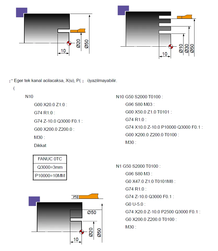
4. R on the first line: peck retract amount
The R1.0 in G74 R1.0 sets how far the tool retracts after each Z-direction plunge. This value is modal, retained until a new value is written, and can also be defined by a parameter; the G74 R command in the program can change the corresponding parameter value. In the 0i-C and 21i sources this value is associated with parameter 5139, and on old Series 0/00/0-Mate systems with parameter 0722. If R is too small, the chip may not break enough, chips may pack in drill flutes, and the edge may rub the surface. If R is too large, the cycle time grows, unnecessary idle motion occurs on each peck, and the impact on the drill re-entering the hole can increase.
5. R on the second line: relief at the bottom of the groove
The R0.2 in G74 X40.0 Z-8.0 P3000 Q2000 R0.2 F0.10 is different from the first-line R; it is the relief amount the tool applies at the bottom of each groove cut. According to the FANUC manual the meaning of the two R values is distinguished by whether X or U is present on the second G74 line: if X/U is present the second-line R is Δd, the bottom relief; if only Z-axis drilling is done, R can also set the retract direction.
6. The P address: shift amount in X
P3000 sets how far the tool is shifted in X after each Z-direction drilling or groove move. It is usually written unsigned. With a 0.001 mm input unit, P3000 = 3.000 mm. Even if the X axis is diameter-programmed, the FANUC manual defines Δi as a radius amount; therefore the P value should not be entered twice as large as if it were a diameter difference.
7. The Q address: peck depth in Z
Q2000 sets how much is cut in Z on each step. In a 0.001 mm input system, Q2000 = 2.000 mm. The Q value is entered positive and unsigned; the real motion direction is determined by the direction of the Z or W target, and it cannot be zero. If the last peck amount is smaller than Q, the control cuts the remaining distance and completes the cycle at the target Z point.
8. Use of X, U, Z and W
Absolute dimensioning: G74 X40.0 Z-8.0 P3000 Q2000 R0.2 F0.10 — X40.0 is the final X coordinate, Z-8.0 the final Z coordinate. Incremental dimensioning: G74 U-20.0 W-10.0 P3000 Q2000 R0.2 F0.10 — U-20.0 is the incremental distance in X from the start, W-10.0 the incremental distance in Z. Absolute and incremental commands must not be mixed.
9. The key difference between pure drilling and grooving
| Feature | Drilling only | End-face grooving |
|---|---|---|
| Example | G74 Z-30.0 Q5000 F0.12 | G74 X40.0 Z-8.0 P3000 Q2000 R0.2 F0.10 |
| X/U | None | Present |
| P | None | Present |
| Motion | Peck drilling in Z only | After Z pecks, shift in X, repeat up to the target X |
The manual clearly states that when X/U and P are removed, the cycle works as Z-axis drilling only.
10. Parameters related to G74
10.1 Old FANUC Series 0/00/0-Mate — Parameter 0722 (GROVE)
Parameter 0722 (GROVE) sets the return amount in the G74 and G75 cycles. The metric input unit is 0.01 / 0.001 / 0.0001 mm depending on the control increment system, with a value range of 0–99999999. The old Series 0-TD parameter manual shows parameter 0722 directly for G74/G75.
10.2 FANUC 0i-C, 0i Mate-C and 21i — Parameter 5139
Parameter 5139 sets the peck return amount in the G74 and G75 multiple repetitive cycles (two-word numeric value, metric 0.001 mm, inch 0.0001, range 0–99999999). When G74 R1.0 is written in the program, this modal value is not only used but, according to the manual, the corresponding parameter value can also be changed by the program command. Important result: the G74 R value written by a previous program can remain in later programs; therefore it is safer to write the first-line R value explicitly in G74 programs.
10.3 FANUC 0i-D — Parameter 5106 bit GFX
On 0i-D systems with the grinding-cycle option, 5106#0 GFX can determine the meaning of the G71–G74 codes. If GFX=0, G74 is a lathe multiple repetitive cycle command; if GFX=1, G74 is interpreted as a grinding-cycle command. When this parameter is changed, the CNC power must be turned off and on; this setting matters only on special systems that have the grinding option.
11. G-code system difference
| G-code system | End-face peck drilling code |
|---|---|
| System A | G74 |
| System B | G74 |
| System C | can be G76 |
A program taken from another machine should not be copied directly. In FANUC tables the G74 function is shown as G76 in System C. Also, on grinding machines G74 can mean a different grinding cycle.
12. G74 program example — Peck drilling from the center
%
O7401
(G74 PECK DRILLING)
G21
G18
G40
G99
T0303
G97 S900 M03
M08
G00 X0 Z2.0
G74 R1.0
G74 Z-32.0 Q5000 F0.12
G00 Z50.0
M09
M05
M30
%
G97 S900 M03a constant 900 rpm spindle speed (constant rpm is used for drilling).G00 X0 Z2.0the drill is brought to the center axis and in front of the face.G74 R1.0a 1 mm retract after each peck.G74 Z-32.0 Q5000 F0.12the tool advances to Z-32 in 5 mm pecks.
13. G74 program example — End-face grooving
%
O7402
(G74 END FACE GROOVING)
G21
G18
G40
G99
T0404
G97 S700 M03
M08
G00 X70.0 Z2.0
G74 R0.5
G74 X50.0 Z-6.0 P3000 Q2000 R0.2 F0.10
G00 X100.0 Z50.0
M09
M05
M30
%
In this example the tool goes to Z-6 in 2 mm pecks in Z, makes a 0.2 mm relief at the bottom, returns to the start Z position, shifts 3 mm radially in X, and repeats the same motion up to X50.
14. G74 alarm and error solutions
P/S 062 — ILLEGAL COMMAND IN G71–G76
This is the most basic program alarm related to G74. The FANUC alarm description shows the following four cases directly among the P/S062 causes for G74/G75:
- P entered negative: faulty
... P-3000 Q2000 ...; P (Δi) must be unsigned →P3000. - Q entered as zero: faulty
G74 Z-30.0 Q0 F0.12; Q is the Z peck depth and cannot be zero →Q5000. - A move command given on the relevant axis while P or Q is zero:
P0while an X move is wanted, orQ0while there is a Z move, is invalid. - Second R entered negative when defining the bottom relief direction: if a groove is made using X/U and P, the second-line Δd must be entered positive →
R0.2.
Wrong tool paths that can appear without an alarm
The tool does not shift in X at all: X or U not written, P not written, the X start and end values are the same, or P entered in the wrong unit. Peck depth much larger than expected: Q written wrongly as if it were a decimal address, Q50000 entered instead of Q5000, or the input increment system misjudged. The tool cuts the groove in the wrong direction: the direction of the X/U target is wrong, absolute X and incremental U are mixed, or inside/outside diameter directions are confused. The tool retracts too much on each peck: the first-line R is large, parameter 5139/0722 is at an unexpected value, or the previous modal value is used because the first G74 R line was not written. The tool relieves to the wrong side at the bottom: the function of the second-line R is misunderstood, the R sign is chosen wrongly even though X/U is not used, or the groove-cutter direction does not match the program.
15. Key points to watch when using G74
- X/U and P are not used for drilling; for end-face grooving X/U and P are defined together.
- P and Q are written in most FANUC formats without a decimal, in the smallest input unit.
- P is a radius amount in X; Q cannot be zero.
- The first R is the peck retract, the second R is the tool relief at the bottom of the groove.
- Because the first R is modal, it is safer to write it explicitly in every program.
- For drilling with a drill, the tool must be set toward the X0 center; on deep holes chip evacuation and coolant must be checked.
- The first trial should be run in single block and at a low override.