
When a CNC operator picks up a finished workpiece, some surface defects and dimensional errors are immediately visible. The tool or the program usually gets the blame; in many cases, however, the real cause is mechanical wear in the axes and the tuning of the servo parameters.
In this guide we start from the visible defects on the part, narrow down the root cause, and look at the critical parameters that a service engineer works with on Fanuc controls.
Which Fanuc Models Does This Guide Apply To?
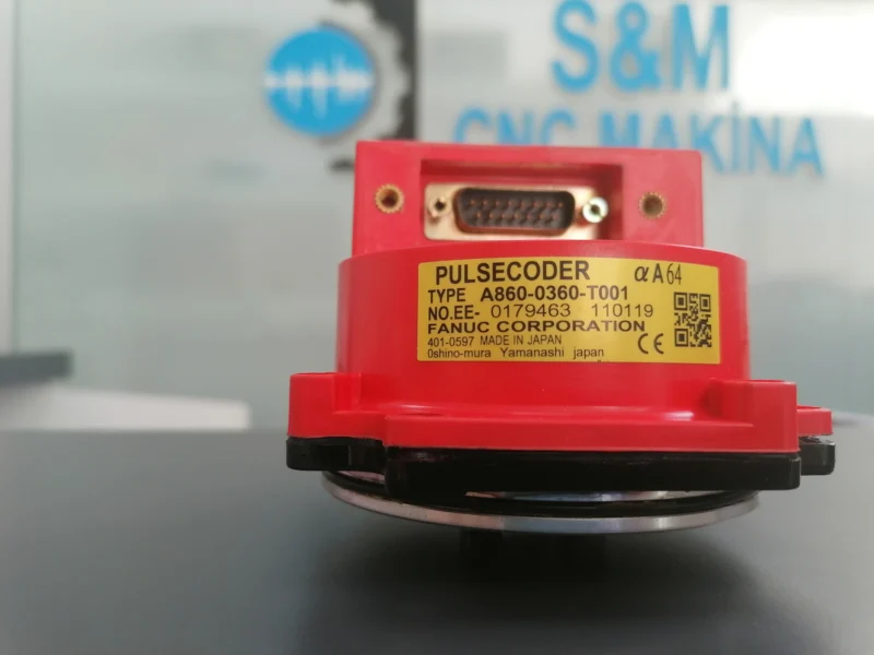
Parameters such as 1851, 2043 and 1825 are not specific to a single series. The same parameter structure is largely shared across all digital-servo Fanuc controls: the 16i, 18i, 21i and 0i series (0i-MC/MD/MF) up to the more recent 30i/31i/32i series.
That said, bit-level definitions in particular can differ between servo software versions. Before changing anything, always confirm the exact definition in the FANUC servo parameter manual for your machine (for example the B-65270EN series).
1. Symptom: Circles Come Out Oval or Dimensions Differ Between Axes (Backlash)
How does the operator recognize it?
- You machine a circular pocket or flange. Measured with a caliper or micrometer, the dimension along X does not match the dimension along Y; the part is oval instead of perfectly round.
- At the exact axis-reversal points (the 12, 3, 6 and 9 o’clock positions) you see a distinct flat spot or step on the machined surface.
What is happening in the background?
The ball screw, its bearings or the couplings have worn over time and lost play has developed. The motor turns, but because of the mechanical clearance the axis momentarily misses part of the motion at every direction reversal. On a ballbar (circularity) test this shows up as steps at the axis transition points.
Fix and service action
If the mechanical clearance is not excessive (the ball screw is not at the end of its life), the error can be reduced electronically inside the Fanuc control:
- Relevant parameter:
1851(backlash compensation amount for cutting feed) - Additional note: parameter
1852defines a separate backlash compensation value for rapid traverse; this separation is enabled with the corresponding option bit. - Service action: measure the actual axis clearance with a dial indicator or ballbar, then increase
1851gradually based on the measurement.
Keep in mind that electronic compensation is a limited correction, not a cure for mechanical wear. If the clearance has grown large, the ball screw, nut or bearings need to be replaced.
2. Symptom: Nicks or Burr Marks at Direction Changes (Reversal Spike)
How does the operator recognize it?
- Especially in mold work and on curved (radiused) surfaces, small sharp scratches, nicks or dot-like witness marks remain on the part exactly where an axis reverses direction.
- Running a fingernail over the part, you feel a sharp ridge or mark at those transition points.
- The lines become very obvious during polishing of mold surfaces.
What is happening in the background?
This is known as a “reversal spike”. As the axis passes from the positive to the negative direction, the servo motor momentarily hesitates while overcoming friction and then reacts sharply, leaving a mark on the part. On circularity testers such as the Renishaw Ballbar, the defect appears clearly as sharp outward spikes at the quadrant transitions.
Fix and service action
First parameter to try: 2043 (PK1V – velocity loop integral gain).
Technical note: some field sources refer to 2043 as “velocity feed forward”, but in the official FANUC servo documentation this parameter is the velocity loop integral gain. Velocity feed-forward is a separate function – it is enabled with bit 1 of parameter 2005 and its coefficients are set in parameters 2068 / 2069.
Service note: if this value is raised too far, the axes may start to vibrate or become unstable during rapid traverse (G00) or handwheel jog. Excessive increase can also produce negative (inward) spikes.
If that does not solve it – the backlash acceleration function: the following settings are used in field practice to soften the motor dynamics at direction reversal:
- Bits 3 and 5 of parameter
2003are set to1. - Bit 6 of parameter
2005is set to1. - Bit 6 of parameter
2009is set to1. - As an example field approach,
2021(load inertia ratio) is raised by about +50,2048(backlash acceleration amount) by +150/+200 and2071(backlash acceleration time) by +30 units.
Important warning: the bit definitions and increments above are compiled from field practice; they can differ between servo software versions and control series. Before applying them, confirm the bit definitions in the official FANUC servo parameter manual for your machine and back up all current values. After the change, repeat the ballbar test under identical conditions to verify the improvement.
3. Symptom: Corners Round Off at High Feed or the Surface Shows Waviness (Servo Loop Gain)
How does the operator recognize it?
- At low feedrates the machine cuts fine, but as the feedrate increases, sharp corners and radii lose their form – corners come out more rounded than programmed.
- Periodic micro-level waviness (like vibration marks) appears on the surface.
- The machine runs roughly or with vibration during high-speed circular movements.
What is happening in the background?
The position loop gains of the servo axes are either too low or mismatched between axes. The axes cannot follow the commanded path fast enough, and when interpolating axes respond differently from each other, the contour is distorted.
Fix and service action
Relevant parameter: 1825 (servo loop gain – position loop gain per axis). Its unit is 0.01 s⁻¹ and the typical standard value is 3000 (30 s⁻¹).
The basic relationship between loop gain and following error can be summarized as:
Following error (mm) ≈ Feedrate (mm/min) / (60 × Loop gain (1/s))

Example: at F1000 with a loop gain of 30 1/s
following error ≈ 1000 / (60 × 30) ≈ 0.55 mm
Service action: the gain values are optimized for the mechanical structure of the machine. The most critical rule: all interpolating axes must use the same loop gain value. If the gains differ, circles come out oval and corners lose their form.
If the value is set too high, the axes start hunting and vibrating; if it is too low, the following error grows and corner rounding increases.
A Golden Rule for Operators and Machinists
When these kinds of part defects start appearing, check cleaning and lubrication before calling the service engineer. Dry guideways or binding telescopic covers increase friction and upset the balance of these parameters.
If everything is mechanically clean and properly lubricated, share the symptom-to-parameter mapping in this guide with your service engineer so the diagnosis can be made precisely instead of by trial and error.
Before Changing Any Parameter
- Back up all current parameter values.
- Test changes on one axis at a time, in small steps.
- Prove the program first in graphic/simulation mode, single block and low feedrate.
- If possible, repeat the ballbar measurement before and after the change under identical conditions.
Disclaimer
This content explains the fault-diagnosis logic on Fanuc controls starting from visible workpiece defects. Servo and parameter changes directly affect physical machine motion and must only be carried out by qualified, experienced technical personnel. The same parameters can behave differently across Fanuc series and servo software versions; the machine tool builder’s and FANUC’s official manuals always take precedence. Fanuc and Renishaw are trademarks of their respective owners; this content is prepared independently for educational purposes.