
📷 IMAGE AREA — Measuring backlash with a dial indicator on the M70 and the magazine alignment in M19 spindle orientation
Recommended size: 1200×630 px (16:9, hero) · WebP/JPG · <150 KB · filename: mitsubishi-m70-backlash-m19-setting.webp · alt: Mitsubishi M70 backlash measurement and M19 spindle orientation magazine alignment
On the Mitsubishi M70 control, two different positions must be set correctly during a tool change: the spindle stopping at the correct angular position and the Z axis reaching the magazine tool-change height correctly. These two are related but not the same: M19 spindle orientation stops the spindle at the angle suited to the tool-holder channels; the Z-axis tool-change position makes the spindle and the tool in the magazine meet at the same height; backlash setting lets the CNC compensate the mechanical play that occurs on axis direction changes. Although these can be done from the parameter screen, just entering a parameter number and changing a value is not enough — mechanical alignment, approaching the magazine manually, marking and a controlled test are required.
1. What is backlash setting?
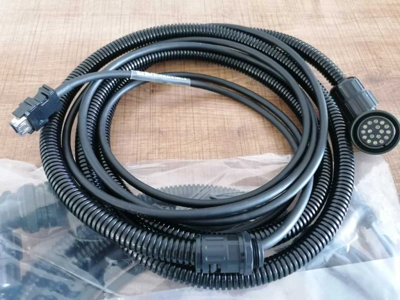
Backlash is the position loss that occurs, when an axis changes direction, due to mechanical play in the ball screw, nut, coupling or bearing system. For example when the X axis moving in plus stops and switches to minus, the table may not move for a short time even though the motor has started turning; this loss is backlash. The problems it causes: ovality in circular pockets, dimensional offset at corners, a different dimension when a point is reached from different directions, a direction-change mark in circular interpolation, a step on precise surfaces and a position difference at hole centers.
2. Mitsubishi M70 backlash parameters (#2011 / #2012)
The M70/M700 system uses two separate parameters for standard backlash compensation. #2011 G0back — the backlash compensation used during rapid moves and manual axis moves; generally effective in G00 rapid, JOG, manual axis moves and reference/rapid positioning. #2012 G1back — the backlash compensation used during cutting feed; generally effective in G01 linear cutting, G02/G03 circular moves and direction changes made with cutting feed. So changing only #2012 may not solve the whole backlash problem; whether the error occurs in a rapid move or a cutting move must be determined.
3. Are the backlash parameters bit parameters?
#2011 and #2012 are not bit parameters; they have no individually toggled bits. A numeric compensation value is entered directly. But how many millimeters the entered number corresponds to depends on the control’s axis resolution and interpolation unit. For example on some machines 10 = 0.010 mm; but this value must not be assumed exactly the same on all M70 machines (the unit can be 1 micron, 0.1 micron or a different resolution). So before changing, the current value must be saved, the axis resolution checked, small values tried and the result measured with a dial indicator.
4. Which direction does the axis go when the value is increased?
The backlash parameter does not work like a normal axis position; writing a larger number does not make the axis move continuously in plus/minus. The control applies the set amount of extra compensation only when the axis direction changes. If the compensation is low, play remains on a direction change; if correct, the dimension is equal when a point is reached from plus and minus; if excessive, the axis over-compensates the play and a dimensional error occurs in the opposite direction. So the correct setting is made according to the measurement result, not just by increasing/decreasing the number.
5. Variable backlash parameter check (#2121)
Some M70 systems can use a variable backlash function. If #2121 is active, the standard #2011 and #2012 values may not work as expected. Generally: 0 = variable backlash off, 1 = variable backlash active, 2 = continuous variable backlash active. When variable backlash is active, compensation can be applied by different tables or positions; so if the machine behavior does not change even though #2011/#2012 are changed, #2121 and the machine’s variable backlash settings must be checked first.
6. How is backlash set?
Backlash is not set by estimation; it must be measured with a dial indicator. Required equipment: a precise dial indicator, a magnetic/fixed measuring stand, a solid clean table surface, a measurement table. Measurement steps: send the machine to reference → place the indicator parallel to the axis → approach the indicator from one direction and zero it → move the axis a set amount in the same direction → reverse the direction → measure the amount by which the indicator does not react even though motion has started on the CNC → repeat several times and verify the results are close → change #2011 or #2012 in small steps per the measured value. After setting: reach the same point from plus and minus and compare the indicator difference; test G00 and G01 moves separately; do a circular pocket/circle test; check whether the measurement changes at different speeds. If the backlash value comes out unstable, the problem is not just the parameter — the ball-screw nut, coupling, bearing, linear rail or mechanical connections must be checked.
7. What is M19 spindle orientation?

The M19 command stops the spindle at a specific angle. During an automatic tool change, the tool-holder tabs/channels inside the spindle must be at the same angle as the tool-change arm and the tool in the magazine. If the spindle stops at the wrong angle: the magazine tool cannot seat fully into the spindle, the tool-change arm can be strained, the tabs may not meet the channels, a tool-changer alarm can occur, and the arm/spindle/tool-holder can be damaged.
8. There are two different positions in M19 setting
1) Spindle angular orientation — the spindle rotates to bring the tool-holder notches to the angle suited to the magazine/tool-change mechanism; this is done with the M19 command. 2) Z-axis tool-change height — the tool under the spindle and the tool in the magazine must meet at the same height; this is the Z-axis tool-change (or second reference) position. If one of these two is correct and the other wrong, the tool change still does not happen properly.

9. About the M19 parameter numbers (3107 / 3108)
Field notes mention parameter 3107 or 3108 for M19 orientation on some machines. But these numbers must not be assumed standard for all M70 machines; the parameter number can vary by the spindle-drive model, encoder type, the builder’s PLC program, the magazine structure, the tool-change mechanism and single/multi-point orientation. So if the description does not show something like orientation/spindle position when 3107/3108 is opened on the parameter screen, the value must not be changed. On some machines the orientation angle can be set not from a CNC parameter but from a PLC constant or the spindle drive.
10. How is M19 orientation set?
M19 setting is usually done by controlled trial and observation. Increasing the parameter value may not rotate the spindle in the same physical direction on every machine (because of the encoder direction, belt transmission and spindle structure, increasing can correspond to the right on some machines and the left on others). Sequence: (1) Save the current value (parameter number, current value, the spindle’s stopped position; a photo of the screen if possible). (2) Put a thin pencil reference mark on the spindle body and a fixed point (to observe the direction and amount when the parameter changes). (3) Give M19 from MDI and wait for the spindle to stop fully. (4) Make a very small change (e.g. 100 → 101 or 99); avoid large changes. (5) Run M19 again and check how far the pencil mark shifted right/left (this first test determines the direction of increasing). (6) Approach the magazine manually to the spindle and compare the tool-holder notches with the spindle notches; if not in line, change the parameter again in small steps.
11. How is the magazine approached manually?
Many tool magazines have a switch, a brake-release mechanism or a mechanical turning point for manual movement on the magazine/tool-change motor. General logic: put the machine in a safe maintenance state → stop automatic operation → give M19 to the spindle and verify it has fully stopped → release the magazine motor’s brake/manual mechanism per the builder’s procedure → move the magazine motor slowly with the manual switch → approach the magazine tool to the spindle → observe the alignment of the tabs and notches → stop the motion if the mechanism is strained → if the notches are fully aligned, the M19 position can be accepted as correct. During this, the magazine motor must not be strained and the automatic tool changer must not be run at the same time.
12. How is the M19 alignment checked?
During the check, three points must match: the tab/guide channel inside the spindle, the notch of the tool holder, and the gripping direction of the magazine/tool-change arm. If, when the magazine is manually approached, the tool holder can enter the spindle naturally, the angular alignment is correct. Wrong-orientation signs: the tool holder does not seat fully in the spindle; the magazine arm presses to the side; the notch does not meet the spindle tab; there is mechanical strain on approach; the tool enters the spindle at an angle; the tool changer jams on retract.
13. Z-axis tool-change position (#2038)
Even if the M19 angle is correct, if the Z axis does not reach the correct tool-change height, the magazine and spindle cannot meet at the same level. The Z-axis tool-change position can be defined on some machines as the G30 second reference position, a builder-special parameter, a PLC constant or a tool-change macro position. Field notes mention parameter #2038 for some M70 machines; but this number may not have the same function on all machines. So when #2038 is opened, the value must not be changed without checking the description and the axis column.
📷 IMAGE AREA — In the M19 position, the alignment of the spindle notch with the magazine tool holder and the Z tool-change height
Recommended size: 1200×675 px (16:9) · WebP/JPG · <150 KB · filename: mitsubishi-m70-m19-magazine-alignment.webp · alt: Mitsubishi M70 M19 spindle notch magazine tool holder alignment and Z height
14. G30 tool-change position
The G30 command sends the machine to the second, third or fourth reference position. General use: G30 P2, G30 P3, G30 P4. If no P value is written, most systems use the second reference position. The tool-change Z height can often depend on the second reference position; but the machine builder may use a different reference point or a special macro.
15. If the Z position is increased, does it go up?
The physical result of increasing/decreasing the Z position parameter depends on the machine coordinate direction. On vertical machining centers, Z+ usually means the spindle moving up away from the part, and Z− moving down toward the part. Example: if the old position is Z-500.000 and the new is Z-499.000, the new value is 1 mm more positive and in the standard scheme the spindle goes ~1 mm up; if the new is Z-501.000, it is 1 mm more negative and goes ~1 mm down. But this direction must always be verified on the machine: pressing the Z+ key briefly in JOG mode, check whether the machine coordinate increases and which way the spindle physically moves.
16. How is the Z tool-change height set?
(1) Save the current value (the tool-change Z position parameter/reference value; photo or written record). (2) Run M19 from MDI and wait for the spindle to stop at the tool-change angle. (3) Send the Z axis to the tool-change position — per the machine procedure, G30 or a special command, e.g. G91 G30 Z0 (G91 incremental mode, G30 Z0 sends Z to the defined reference position); this command must be run only after the machine’s G30 usage is verified. (4) Approach the magazine manually (slow the motion before contact). (5) Check the height by eye: the center of the magazine tool, the center of the spindle tool pocket, the gripping height of the tool holder and the axis of the tool-change arm — the tool holder must enter without tilting up/down. (6) Make a small value change (e.g. 0.1 mm or suited to the resolution); do not make a large change. (7) Test again: retract the magazine, bring Z to a safe position, call G30/the tool-change position again, run M19 again, approach the magazine manually again, check the height. Repeat in small steps until the correct alignment is reached.
17. How are M19 and the Z position checked together?
For a correct tool change, both the angle and the height must be checked at the same time. Correct-alignment signs: the magazine tool approaches the spindle straight; the tabs meet the notches; the arm does not press up/down; the magazine motor is not strained; the tool enters easily; no jamming on retract; the M19-complete signal forms properly. Wrong Z-height signs: on approach the tool is strained up/down; the tool holder comes to the entry at an angle; the arm creates vertical pressure; the tool makes noise on entry; the pull system is strained. Wrong M19-angle signs: the notches do not meet even though the height is correct; the tool holder does not enter without being rotated; the arm presses to the side; the spindle tabs hit the notch.
18. Automatic tool-change test
After manual alignment is complete, a full-automatic high-speed test is not done directly. Recommended order: save the final parameter values → return the magazine mechanism to a safe position → bring the brake/manual mechanism back to normal operating state → check that no switch/attachment is left on the machine → move the axes to a safe position → do the first tool change at low speed and under control → watch it in single block/maintenance mode if possible → be in a position with easy access to the emergency stop → stop if there is unusual noise/strain → re-check the alignment at several different stations. If a setting correct at one station is not correct at all stations, the magazine center, tool pockets or mechanical reference setting must be checked.
19. What not to do during the setup
- Do not make changes without saving the current parameter values; do not test with large values.
- Do not run automatically with the magazine brake released; do not move Z at rapid while the magazine is near the spindle.
- Do not approach the magazine to the spindle before M19 is complete; do not force the mechanism if the tool holder is strained.
- Do not set backlash just by eye.
- Do not change unknown bits without the builder’s documentation; if the parameter description differs, do not rely on number similarity alone.
- Do not disable protection or interlock settings to silence an alarm.
20. Overall assessment
On the M70 system, the tool-change setup is not just a single parameter change. For a correct setting, the spindle M19 angle, the Z-axis tool-change height, the magazine mechanical position, the tool-holder notches, the tool-change arm and the spindle encoder/orientation signal must be evaluated together. When the M19 value is increased, which way the spindle turns may not be the same on every machine; so the current position is marked, a small change is made and the result observed. When the Z position is changed, whether the spindle moves up or down must be verified from the machine coordinate direction. In backlash, #2011 and #2012 are used for separate purposes; an estimated value must not be entered without measurement.