
You have just bought a new CNC machine — or the machine you have used for years has started producing oval holes. The corners of square pockets do not match, the finished surface shows marks at regular intervals, or the same program produces different dimensions in different areas of the table.
Where is the problem? In the cutting tool, the program, the workholding, the operator, the measuring instrument — or in the machine’s axis movements?
The ballbar test (sometimes searched as “ball bar”) is not a magic device that answers this question by itself. But by measuring the circular path produced when two axes move together, it quickly narrows down the source of many problems related to servo behaviour, geometric alignment, backlash, scaling and motion transmission. In most cases, setup and measurement take less than half a day.
One of the most widely used systems in the industry is the Renishaw QC20 ballbar; the explanations in this article are based on general ballbar principles.
Independence note: Renishaw and QC20 are trademarks of their respective owner. This content is prepared for independent educational purposes; there is no representation, sponsorship or endorsement relationship between Mentor CNC and the trademark owner.
1. What exactly does a ballbar test measure?
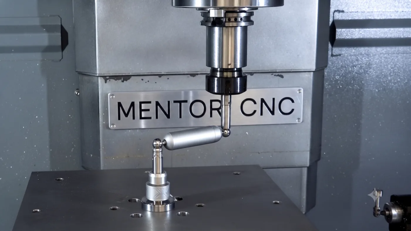
A ballbar is a telescopic measuring sensor with precision spherical joints at both ends. One end attaches to the machine table, the other to the spindle. The CNC is programmed to run circular interpolation at a defined radius, clockwise and counter-clockwise; the device records the micron-level differences between the programmed ideal circle and the circle the axes actually produce.
Ideally the X and Y axes move in perfect harmony and the plot comes out close to a perfect circle. In reality, reversal backlash, servo following delays, guideway problems, out-of-squareness between axes and scaling mismatches distort the shape of the plot.
Large-radius, low-feed tests emphasize geometric errors; small-radius, high-feed tests make servo and dynamic behaviour more visible.
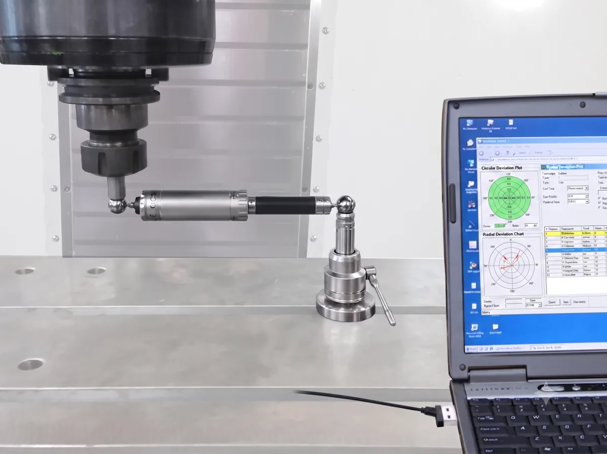
A ballbar report typically evaluates: circularity deviation, positioning tolerance, backlash, servo mismatch, squareness between axes, scaling mismatch, straightness and lateral play, cyclic error, reversal spikes, vibration and low-speed stick-slip behaviour.
2. Why do these errors occur on CNC machines?
Here is an important fact: these errors do not occur only on old, worn-out machines.
- They can occur even on a brand-new machine. Even if the machine was perfectly adjusted at the factory, transport shocks, crane lifting, frame twist and an unsuitable floor can change its geometry.
- They can appear after replacing bearings, ballscrews or guideways. Even when the mechanical work is done correctly, axis behaviour changes and needs re-verification.
- They can follow a crash. After a tool, fixture or table collision the machine may look fine from the outside while its axis geometry is disturbed.
- They can result from removing the table or moving the machine. Even a move of a few meters inside the same shop can change foot loads and frame balance.
- They can develop silently over time. Guideway wear, insufficient lubrication and thermal cycles grow dimensional errors unnoticed.
This is where the real value of the ballbar test lies: it performs a numerical, comparable “health scan” of the machine before parts start going to scrap.
3. The typical failure scenario without a ballbar: wasted money and time
A common story on a machine that starts producing dimensional errors goes like this:
A repairman is called; he says “the ballscrew is worn out” and the screw is replaced. The deviation continues. Another repairman replaces the bearings. The problem persists. A third one says “the machine has crashed” and dismantles the table. A fourth one declares “the machine has lost its squareness” and starts adjusting the geometry.
The result: heavy parts and labour costs, days of downtime, settings changed on top of each other — and, very often, a dimensional problem that is still unsolved. Worse, every intervention makes the real root cause harder to find.
The correct approach is exactly the opposite: when unexplained dimensional errors begin, run a ballbar test before any part is replaced and before any parameter is touched. The test takes less than half a day and numerically separates possibilities such as backlash, squareness, servo and cyclic error. That way no money is wasted on unnecessary ballscrew or bearing replacements, and the machine’s working settings are not disturbed.
4. Does your machine have a sizing error? Taper? A spiral pattern? The fastest way to diagnose it
You’re boring a hole on a vertical machining center and it doesn’t come out perfectly round — slightly larger in one direction, slightly narrower in the other, a faint oval or taper. Or on a lathe, the same program with the same tool sometimes produces a part right on size and sometimes a few percent off on one side of the axis. The operator says “something’s off on the X axis,” but nobody can say exactly where it comes from.
At this point a shop usually takes one of two paths: trial and error, or measurement. Both can get you to an answer eventually — but they differ hugely in time, cost and certainty.
Checking with a dial indicator: the first thing people try, and where it falls short
Without a ballbar on hand, an experienced technician’s first move is usually to mount a dial (magnetic-base) indicator. It’s attached to the table or the spindle, the axis is jogged back and forth by hand, and the technician checks for play in the ballscrew-nut, the way-carriage fit, or the bearings. This method is real and useful — it catches plenty of simple play and looseness issues.
But by its nature a dial indicator has three important limits:
- It measures one axis, at one point, at a time. The indicator shows what’s happening along the direction it’s mounted on — but the error most often doesn’t sit squarely on the X axis or the Y axis; it shows up in the diagonal zones where both axes are moving together. Checked one axis at a time, the machine can look perfectly fine, while the same machine shows a clear error the moment both axes interpolate in a circle.
- It cannot show where along the ballscrew the wear is. If a ball screw has localized wear in the recirculating balls at one particular section, the indicator only reports the play at the single position it happens to be measuring — not how that play changes along the full travel, and not where the error actually concentrates.
- It cannot separate a servo problem from a synchronization problem. Even after a bearing is replaced or a gib is tightened, the deviation can persist because of motor response lag, mismatched axis gain settings, or an encoder-related synchronization issue. A dial indicator is a static measurement tool; it cannot show how two axes behave together, dynamically, in motion.
This is why shops so often end up in the same loop: a technician replaces the bearing — the deviation continues; replaces the ball screw — it continues; pulls and reseats the table — it continues. The bearing and the screw may have genuinely been fine; the real source of the error was never actually seen, because a dial indicator was never designed to show it.
Why a ballbar test is the answer: it tests both axes together, in circular motion
The core difference between a ballbar test and a dial indicator is this: instead of moving axes one at a time, a ballbar moves them together through a full circle and records, to micron accuracy, the difference between the programmed ideal circle and the circle the machine actually traces. That lets it:
- Tell you which axis the error is on. By looking at whether the distortion in the plot concentrates at the 0°/90°/180°/270° positions or at the 45°/135° diagonal zones, a ballbar plot separates an error on the X axis from one on the Y axis from one in how the two axes work together. On a lathe the same logic applies between X and Z (and, in some setups, the spindle).
- Show localized wear on the ball screw. Regular, repeating ripples around the circle (cyclic error) usually trace back to eccentricity at a specific point on the ball screw or encoder — exactly the kind of detail a dial indicator cannot see, but a ballbar plot shows clearly.
- Separate a servo-related error from a purely geometric one. The same test is repeated clockwise, counter-clockwise, and at different feed rates. An oval caused by servo/synchronization mismatch changes with direction and speed; a fixed geometric error such as squareness does not. That one comparison alone answers the question “does a bearing need replacing, or does a parameter need adjusting?”
- Put every likely cause into one numeric report. Backlash, squareness, scaling mismatch, servo mismatch, cyclic error and straightness all come out of the same test set as separate, quantified values.
Other precision instruments exist too — a laser interferometer, for instance, measures linear positioning very accurately — but these typically test one axis at a time, statically, point by point. What makes the ballbar so widely used on the shop floor is that it captures the dynamic, two-axis circular motion in a single test, in under half a day, at a comparatively modest cost.
Experienced service technicians can build up a similar instinct over years of trial and error on the floor — a good ear and a good eye can often guess “this sound, this symptom, is probably X.” A ballbar test gets to the same diagnosis without relying on instinct: it’s a numeric, repeatable measurement, which usually means getting there faster and with far less guesswork.
5. Who uses ballbar systems?
The ballbar is not just a machine builder’s instrument.
Production departments: They determine whether a machine matches the tolerances of the part to be machined. In a shop with five vertical machining centers, not all machines have the same accuracy; die and mold finishing can be routed to the most accurate machine and roughing to the others.
Maintenance departments: Instead of reacting after a breakdown, they track performance degradation over time. Regular measurements reveal growing backlash, changing servo behaviour, cyclic error and guideway wear early, enabling predictive maintenance.
Quality departments: When a part measures wrong, they separate operator, program, tool, fixture, probe and measuring-device possibilities before blaming the machine. The ballbar investigates the machine-related possibilities; it does not replace the other checks.
Machine builders and service companies: They use it for new machine verification, factory outgoing inspection, post-maintenance and post-crash verification, and performance comparison between machines. It should not be assumed that this practice automatically applies to every builder and every model.
6. Can anyone perform a ballbar test?
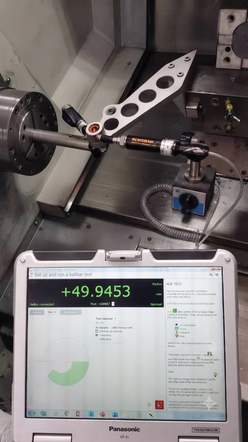
Mounting the device and running a prepared program can be done by a technician with basic training or an experienced CNC operator. Current software guides the user step by step through the setup.
But there are two separate competencies: physically performing the test, and interpreting the result correctly. Distinguishing a machine error from a test setup error takes experience. A bad plot can also be caused by: a mispositioned center mount, a loose magnetic joint, an unclamped spindle, dirty balls, a mismatch between the test program and software settings, a long pause between the two runs, changing ambient temperature, or the cable rubbing during the test.
For this reason it is wrong to change servo parameters or enter backlash compensation just by looking at the plot. Repeatability must be verified first.
7. Should you request a ballbar report with a new CNC machine?
There is no universal rule that automatically obliges the builder to hand a ballbar report to the customer with every new machine. ISO 230-4 defines circular test methods; whether the report is delivered is mostly determined by the purchase contract, the technical specification and the acceptance protocol.
Our advice is clear: especially if the machine is imported and no factory test report was offered to you, have a circular-test clause added to the specification at order time and request two reports:
- FAT (Factory Acceptance Test): at the builder’s plant before shipment
- SAT (Site Acceptance Test): at your site after final installation and leveling
If both tests are run under the same conditions, the effect of transport and installation on the machine becomes clearly visible.
Example specification clause: “The machine shall be subjected to a circular interpolation performance test at the manufacturer’s facility before shipment and after final installation at the customer’s site. Tests shall be performed in the XY plane and, where the machine structure allows, in the XZ and YZ planes. The test radius, feed rate, test position, ambient temperature, device serial number and calibration data shall be stated in the report; clockwise and counter-clockwise results shall be delivered together with the raw measurement files.”
The report should contain at least: machine brand/model/serial number, test date, person or company performing the test, device serial number and calibration date, test plane (XY/XZ/YZ), test radius, feed rate, test position in the working area, machine and ambient temperature, CW/CCW results, circularity and positioning values, before/after adjustment reports, raw measurement file, and the standard applied.
A single colourful circle plot delivered as a PDF is not enough for meaningful comparison later.
8. How much does the factory result degrade during transport?
There is no fixed answer such as “the machine degrades by so many microns after transport”. The outcome depends on the machine’s structure and weight, transport locks, crane lifting method, road impacts, the condition of the floor and concrete, foot load distribution, leveling and anchoring, and thermal stabilization after installation.
The factory test is a valuable baseline reference; but the machine arriving at your site must not be assumed to be in the same condition. A machine must be re-leveled every time it is moved — some builders’ installation instructions state this explicitly as mandatory.
📷 ORIGINAL DIAGRAM SLOT — Factory test → transport → installation → site test flow chart
Suggested alt text: cnc machine factory and site ballbar test flow chart
9. If the machine is not level, is the ballbar result wrong?
The important distinction is this: the device does not measure incorrectly — it measures the current condition of a machine whose level and geometry are disturbed.
If the feet are unbalanced or the frame is twisted, the guideways deviate from their ideal lines: the 90 degrees between axes can be lost, straightness errors can appear, different areas of the machine can give different results, squares do not come out square and circles become oval.
- Place the machine on a suitable floor.
- Level it at the points specified by the builder.
- Balance the foot loads.
- Anchor if required.
- Check the geometric alignment.
- Bring the machine to working temperature.
- Run the ballbar test.
- If adjustments were made, repeat the test under the same conditions.
A report taken on an unleveled machine is not garbage — it shows the effect of the existing problem. But level and geometry must be corrected before it is used as the machine’s final acceptance measurement.
10. Does temperature affect the ballbar result?
Yes. The frame, ballscrews, scales and the measuring system are all affected by temperature. If the machine temperature and the expansion coefficient are entered incorrectly, the calculated radius can come out larger or smaller than normal even when the circle looks clean.
For a healthy comparison: complete the warm-up program, keep the ambient temperature stable, reduce local heat sources such as sunlight, heaters or an open door, run compared tests at similar temperatures, and record the temperature in the report. A difference between a cold machine and one that has run for eight hours is not, by itself, proof of a new mechanical fault.
11. When should a ballbar test be done — and when is it unnecessary?
There is no fixed rule such as “mandatory every six months on every machine”. The right approach depends on the situation.
The test is especially worthwhile:
- When buying a new machine (FAT + SAT reports — insist on them, especially for imported machines)
- When the machine is moved (even a few meters within the same shop)
- After leveling or anchoring work (before/after comparison)
- After a crash (visual inspection is not enough)
- After replacing a ballscrew, bearings, linear guideways or an encoder
- Before and after changing servo parameters
- When scrap or dimensional deviation increases without explanation
- Before starting a highly precise job
The test may be unnecessary: If your machine has run for years without problems, dimensions are stable and scrap has not increased, periodic ballbar testing is not mandatory. If you do it, you gain a valuable reference record; if you do not, that is fine too.
The critical rule: If dimensional deviations continue even after bearing replacement and backlash compensation, have a ballbar test done before touching the machine’s parameters and main settings. Mechanical faults in the screw systems and linear guideways, a shifted table or disturbed geometry show up most clearly in this test. Keep the first test as a “reference” and compare later tests against it under the same conditions.
12. What do the plots tell? The most common error types
| Error type | Plot signature | Effect on the part | Probable source |
|---|---|---|---|
| Backlash | Inward/outward step at reversal points | Small flat on circular surface, direction-dependent size difference | Screw-nut clearance, guideway play, wrong compensation, encoder hysteresis |
| Reversal spike | Sharp peaks at axis crossings | Local mark on finished surface | Weak servo response, reversal friction, delayed compensation |
| Scaling mismatch | Oval stretched along X or Y | Circle large on one axis, small on the other | Position corrections, encoder, ballscrew temperature |
| Squareness error | Oval tilted at 45°/135° | Squares out of square, unequal diagonals | Axes not at 90°, frame twist, worn guideways |
| Servo mismatch | 45°/135° oval; changes with direction and feed | Circularity degrading at high feed | Mismatched axis gain settings |
| Cyclic error | Regular waves around the circle | Regularly spaced surface marks | Ballscrew/encoder eccentricity |
| Straightness error | Smooth curved/lobed shape | Size differences across the working area | Guideway bowing, wear, floor/installation problem |
| Stick-slip | Irregular jitter at low feed | Poor surface at low feed rates | Insufficient lubrication, worn guideways |
An important distinction: Squareness and servo mismatch produce similar oval plots. A servo-caused oval changes direction between the CW and CCW runs and grows with feed rate; a squareness-caused oval stays the same in both directions. That is why nobody should declare “the machine has lost its squareness” from a single-direction, single-speed plot.
A test error caused by dirty or worn balls can also produce a three-lobed shape; the difference from a straightness error is that the transitions are sharper.
📷 ORIGINAL DIAGRAM SLOT — Positive/negative backlash plot and scaling vs squareness oval comparison
Suggested alt text: ballbar backlash scaling and squareness error plots
13. Does your machine show these symptoms? Quick checklist
If you answer “yes” to even one of the questions below, it is the right moment to consider a ballbar test before replacing any parts:
- Do circular holes come out large on one axis and small on the other (oval)?
- Do you see small flats near the 0°, 90°, 180°, 270° regions of circles?
- Are the sides of a square pocket correct while the diagonals differ?
- Does the same dimension change depending on whether the axis approaches from plus or minus direction?
- Do waves or marks appear at regular intervals on the finished surface?
- Does an axis move in jerks at very low feed rates?
- Does the same program run correctly in one area of the table and incorrectly in another?
- Does the deviation continue even after entering backlash compensation?
Remember: these symptoms are starting signals, not a diagnosis. An oval hole does not automatically mean a machine error; tool runout, tool deflection, workholding, the program and the measuring method can produce the same symptom.
14. If the result is bad, do we change parameters immediately?
- Verify the test setup and program.
- Repeat the test under the same conditions.
- Check repeatability.
- Examine level and temperature.
- Check lubrication, guideways, ballscrew and mechanical connections.
- Test in different areas of the axes.
- Compare low-speed and high-speed results.
- Do not hide mechanical problems with parameters.
- If parameters must change, back up the old values.
- Re-measure under the same conditions after adjustment.
Backlash compensation does not remove physical clearance; it only makes the control compensate for a specific error. If the ballscrew, nut, bearings or guideways are worn, increasing compensation is not a permanent solution.
15. Is a ballbar test alone sufficient for machine acceptance?
No. The ballbar is a fast and powerful diagnostic and comparison tool, but it does not verify all accuracy characteristics on its own. Depending on the need, machine leveling checks, geometric squareness/parallelism measurements, laser interferometer positioning, axis repeatability, spindle runout and thermal growth, probe checks, rotary axis accuracy, cutting tests and CMM inspection of a machined sample may also be required.
16. Frequently Asked Questions
How long does a ballbar test take?
Setup and measurement usually take less than half a day. Within that time, possibilities such as backlash, squareness, servo and cyclic error are separated numerically — and in many cases a solution proposal becomes clear together with the diagnosis.
My holes come out oval; should I replace the ballscrew right away?
No. First check tool runout, workholding and the program; then run a ballbar test. An oval plot can be caused by scaling, squareness or servo behaviour — and in none of those cases is a ballscrew replacement the solution.
Should I request a ballbar report with a brand-new machine?
Yes — especially if the machine comes from abroad. If a factory report (FAT) was not provided, request it, and have a site test (SAT) done after installation. Comparing the two reports clearly shows the effect of transport and installation.
My machine has run for years without problems; is the test mandatory?
No. If dimensions are stable and scrap has not increased, periodic testing is not mandatory. If you do it, you gain a valuable reference for the future.
I entered backlash compensation and the deviation continues. What should I do?
This is the single most critical moment to use a ballbar. Have the test done before touching parameters and main settings; mechanical faults (screw system, linear guideways, shifted table) show up most clearly in this test.
Does the ballbar test damage the machine?
No. The test uses the machine’s normal circular interpolation motion; there is no cutting load.
Which errors does the test not show?
Spindle runout, thermal growth, tool-holder problems and the absolute positioning accuracy of a single axis are outside the main scope of this test; separate methods (e.g. laser interferometry) are used for those.
Should we do the test ourselves or buy a device?
If you do regular precision production, investing in a device and training can make sense. For one or two measurements per year, hiring a service provider is usually more economical.
Conclusion: a ballbar report is not just a colourful circle
The ballbar test is one of the most practical ways to assess the health of a CNC machine in a short time. Its real value comes not from a single measurement but from comparative tests repeated under the right conditions.
With a new machine, do not rely on the factory report alone; request a site test after installation. And when unexplained dimensional deviations begin, make the diagnosis with a ballbar before replacing parts or disturbing parameters. This approach prevents both unnecessary repair and spare-part costs and the loss of the machine’s working settings.