
Introduction
Most of the metal, plastic, wood and composite parts made today come off CNC machines. Walk into any machine shop: if you see an enclosed machine with a cutting tool moving on its own while the operator watches a screen, you are looking at CNC. This article explains what CNC is, what the letters stand for, where the technology came from, how it grew from 3-axis to 5-axis machining, and how motion is actually created inside a CNC machine. It is written for vocational and engineering students and for operators at the start of their careers, as a foundation for the more advanced topics on this site.
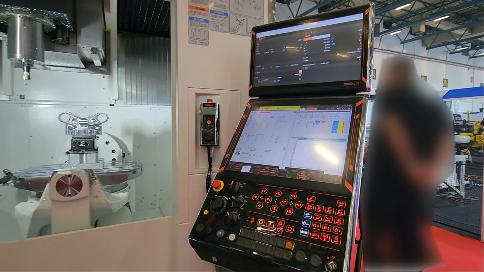
What Does CNC Stand For?
CNC stands for Computer Numerical Control. Letter by letter:
- C — Computer
- N — Numerical
- C — Control
Taken together, CNC means controlling a machine tool with numbers, through a computer built into the machine. The acronym is always spoken letter by letter, “C-N-C”, and always written in capitals.
What Does CNC Mean?
In one sentence: CNC is the control of a machine tool’s movements by a coded program of numbers, letters and symbols, executed by a computer inside the machine. Where the cutting tool goes, how fast the spindle turns and how quickly the tool advances are all defined in a program written in advance. The operator does not turn handwheels; the operator prepares the program, clamps the part, sets the work and tool offsets and supervises the process.
Two words carry the meaning:
- Numerical: motion is described with coordinates, that is, with numbers. A command such as “X50 Z-20” tells the tool exactly where to go.
- Computer: those numbers are read, interpreted and converted into motor commands by a control unit, the machine’s computer. The program is stored in memory, so it can be stopped, edited and resumed.
What Is a CNC Machine? What Is a CNC Machine Used For?
A CNC machine is any production machine that runs under computer numerical control. In everyday language “CNC machine”, “CNC machine tool” and simply “CNC” all mean the same thing. In technical writing, machines that remove material by cutting, such as lathes and mills, are called machine tools; laser cutters, plasma tables, routers and 3D printers are usually just called machines. This site is about machine tools for metal cutting.
What is a CNC machine used for? It turns the part drawn on an engineering drawing into a physical part with a repeatability and speed that no hand-operated machine can match. A shaft, a gear, a mold core, an aircraft structural bracket, a medical implant: each starts as a drawing, becomes a program, and ends as a finished part on a CNC machine.
What Is NC? NC vs CNC
Before CNC there was NC, Numerical Control. On an NC machine the program was punched into paper tape; a tape reader fed each block to the machine as it was read. The control had no memory, so changing the program meant punching a new tape. The logic was built from relays and fixed electronic circuits.
A CNC control has a computer and memory inside it. The program is stored on the machine, edited on screen, checked in a graphic simulation and transferred from a PC. Today, when someone says “NC machine”, they almost always mean CNC; pure NC machines belong in museums.
| NC | CNC | |
|---|---|---|
| Program carrier | Punched tape | Memory, USB, network (DNC) |
| Editing | Punch a new tape | Edit on screen |
| Control logic | Hard-wired circuits / relays | Software (microprocessor) |
| Simulation | None | Graphic toolpath on screen |
| Compensation and cycles | Very limited | Tool offsets, canned cycles, macros |
History of CNC: From the Tracer Mill to 5 Axes
1940s: The problem was a helicopter blade
After the Second World War, aircraft and helicopter parts had complex curves that were very hard to produce on tracer (copy) milling machines. In the United States, John T. Parsons of Parsons Corporation and his chief engineer Frank L. Stulen calculated the coordinates of helicopter rotor blade profiles on punched-card machines and used those coordinate tables to move a milling table with two operators working in sync. It was the first application of the idea of driving a machining motion with calculated numbers. Note where the demand came from: from day one, CNC was born out of defense and aerospace work.
1948–1952: The US Air Force and MIT
In 1948 Parsons won a US Air Force contract for tapered aircraft wing sections, with the MIT Servomechanisms Laboratory as subcontractor for the servo control. The project ended in 1952 at MIT with a three-axis Cincinnati Hydrotel milling machine driven by punched tape. That machine is accepted as the first working numerically controlled machine tool. Parsons’s patent for a “motor controlled apparatus for positioning machine tool” was granted in 1958.
Note: some textbooks describe the 1952 MIT machine as a lathe. The sources show it was a vertical milling machine, the Cincinnati Hydrotel.
1950s: NC in Japan and the first language standards
MIT went on to develop APT, a language that made NC programming easier. In Japan, an NC development team formed inside Fujitsu in 1955 built the first NC and servo system in the Japanese private sector in 1956; in 1972 that team became an independent company, FANUC. The G and M codes we use today took shape in this period and were later defined in the EIA RS-274 and ISO 6983 standards.
1960s–1970s: Memory, the microprocessor and CNC
In the late 1960s ROM memory entered the control unit and programs could be stored on the machine. In the 1970s a minicomputer, and then a microprocessor, moved inside the control: CNC was born. On-screen editing, graphic verification, cutter radius compensation and canned cycles all date from this period. FANUC announced its first CNC in 1972. The machines of the era were mostly 3-axis mills (X, Y, Z) and 2-axis lathes (X, Z).
1980s: From 3 axes to 4
As CAD/CAM software spread, toolpaths began to come straight from the design. Shops needed to machine four sides of a part in one setup, so the vertical machining center gained a 4th axis: a rotary table or indexer (the A axis) mounted on the table turns the part through 90° or any angle while the three linear axes machine each face in turn. Machines with a 4th axis cut setups, time and setup-related error in mold work and series production. Lathes went through the same change with the C axis (angular positioning of the main spindle) and live tooling: the lathe could now drill and mill on the face and periphery of the part.
1990s–2000s: 3+2 positioning and 5-axis simultaneous machining
In the 1990s and 2000s the complex parts of the defense, aerospace and energy industries (turbine blades, aircraft structural parts, weapon system housings, implants) demanded machining on five faces and at compound angles in a single setup. 3+2 axis machining came first: a tilting rotary table positions the part at the required angle, then the three linear axes cut while the rotary axes stay locked. Simultaneous 5-axis machining followed: X, Y and Z move together with two rotary axes (A/B and C) during the cut, so the tool stays normal to a curved surface at all times. Controls of this period made tool center point control (TCP/RTCP), high-speed machining with look-ahead and collision checking standard features.
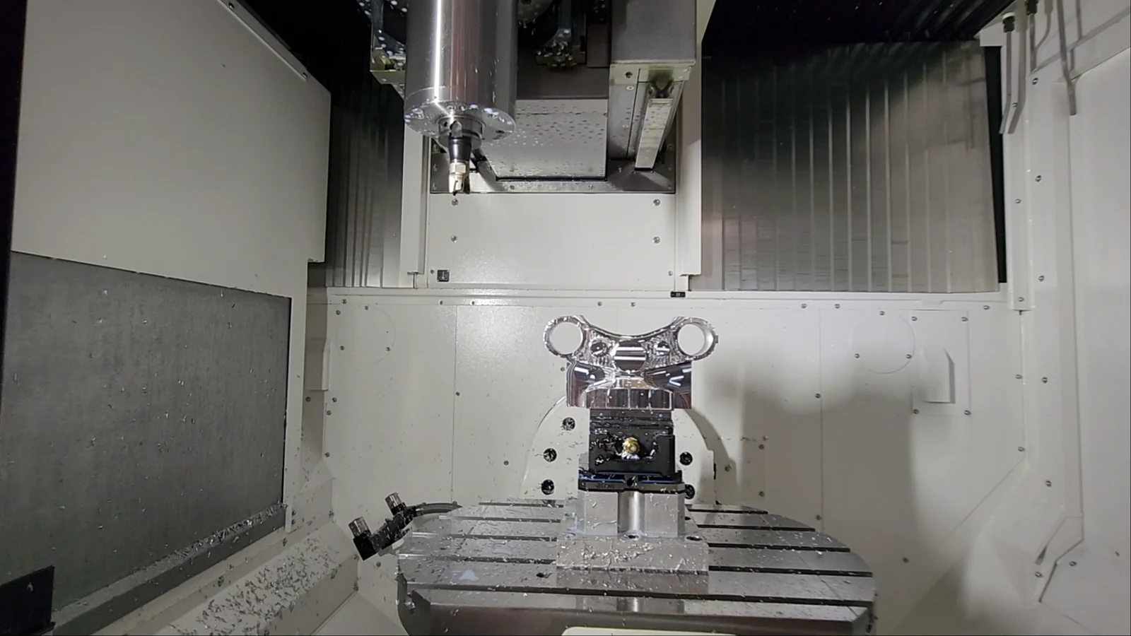
Lathes developed in parallel: the 2-axis lathe gained a C axis and live tooling (often called a “3-axis lathe”), then a Y axis that lets the tool move off the spindle centerline, a sub-spindle that machines the back of the part, and multi-turret layouts. Today’s mill-turn (turn-mill) centers finish the turning, drilling, grooving and milling of a part in one setup; a complex part is completed as if it had been moved from a lathe to a machining center without ever leaving the machine. The turning centers of DMG MORI, Mazak and Okuma are well-known examples of this class.
2010s–2020s: 5-axis becomes the norm
After 2020, demand for 5-axis machines rose sharply, and the defense industry led it. Drone and UAV production, aircraft structural parts, titanium and heat-resistant alloys, and ever more complex geometries meant parts that could not be finished in one setup by 3- or 4-axis milling. For these parts, 5-axis machining centers and mill-turn centers gained ground much faster than the classic 3-axis mill; falling prices and CAM software that made 5-axis toolpaths easy carried the shift into mold shops, medical, automotive suppliers and general job shops. On the research and production side, work continues on configurations reaching 6 and 7 axes through robot loading, additional rotary axes and multi-channel controls.
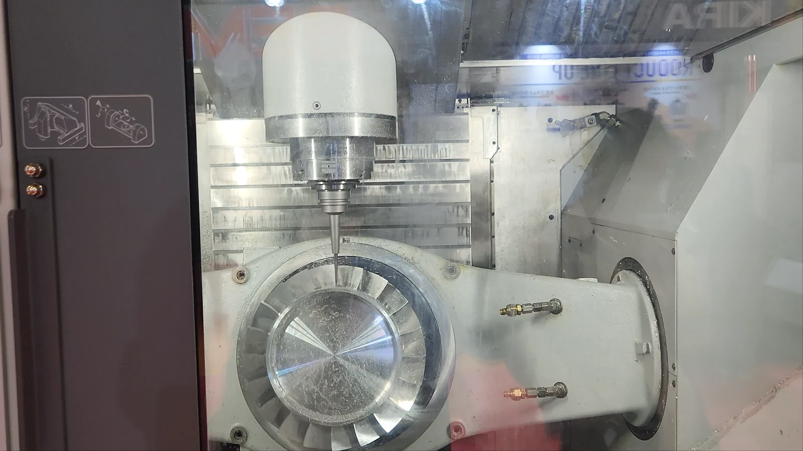
The best place to see where this development stands today is a machine tool show such as MAKTEK Eurasia in Istanbul, held every two years.
MAKTEK Eurasia 2026: See Current CNC Technology at the Show
Turkey’s largest machine tool exhibition, MAKTEK Eurasia 2026, took place from 28 September to 3 October 2026 at the Istanbul Tuyap Fair and Congress Center. Mentor CNC toured the show in 4K: CNC lathes, Swiss-type lathes, 5-axis machining centers, rotary tables, sheet metal and laser cutting machines, industrial robots and automation cells. The video below shows the present-day state of the technologies described in this article.
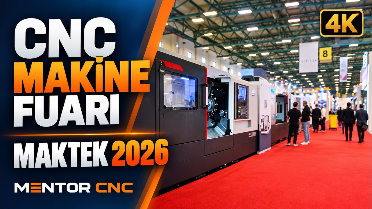
When you press play, the video is loaded from YouTube (Google) servers. Watch on YouTube ↗
This 9-minute tour covers sheet metal and forming machines, CNC machine tools and control panels, Swiss-type lathes and turning centers, CNC machining centers, and automation and workholding systems, in that order. The video runs with music and show ambience; Turkish and English captions describing what is on screen can be switched on from the subtitle menu. The chapter links start the video at the relevant section.
- 0:20 – MAKTEK Eurasia show entrance
- 0:35 – Sheet metal processing and forming
- 3:10 – CNC machine tools and control panels
- 4:55 – Swiss-type lathes and turning centers
- 5:50 – CNC machining centers
- 7:20 – Automation and workholding systems
- 7:55 – Other machine designs and surface finishing
How Does a CNC Machine Work?
Motion in a CNC machine comes from this chain:
- Program: the machining sequence is planned from the engineering drawing and written as a program in G and M codes, by hand or with CAM software.
- Control unit: reads the program block by block, calculates coordinates and speeds, and converts them into motion commands for each axis.
- Servo drive and motor: the command from the control drives the axis motor through a servo amplifier.
- Ball screw and slide: the motor’s rotation is converted into linear motion by a ball screw; the slide (table or turret) moves.
- Feedback: an encoder on the motor or slide reports the actual position back to the control.
Open loop and closed loop
Early machines and small hobby machines use open-loop control: the control sends pulses to a stepper motor, assumes the motor got there, and receives no feedback. Industrial CNC machines run closed loop: the control continuously compares the actual position from the encoder with the commanded position and corrects the motor whenever there is a difference. This is what delivers micron-level repeatability. Tool offsets, work offsets and compensations are all applied inside this chain, in the control.
Axes and the coordinate system
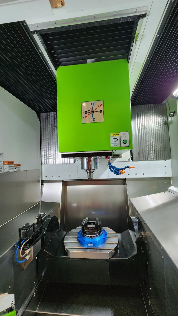
CNC machines work in a Cartesian coordinate system. On a mill the linear axes X, Y and Z are the basis; on a lathe the part rotates, so X (diameter) and Z (length) are enough. Rotary axes are named after the linear axis they rotate about: A about X, B about Y, C about Z. A typical “5-axis” machine is X-Y-Z plus A-C or B-C. Coordinates in the program can be absolute (G90) or incremental (G91); lathes usually program in diameter.
What Is a CNC Lathe? What Is a CNC Mill?
What is a lathe?
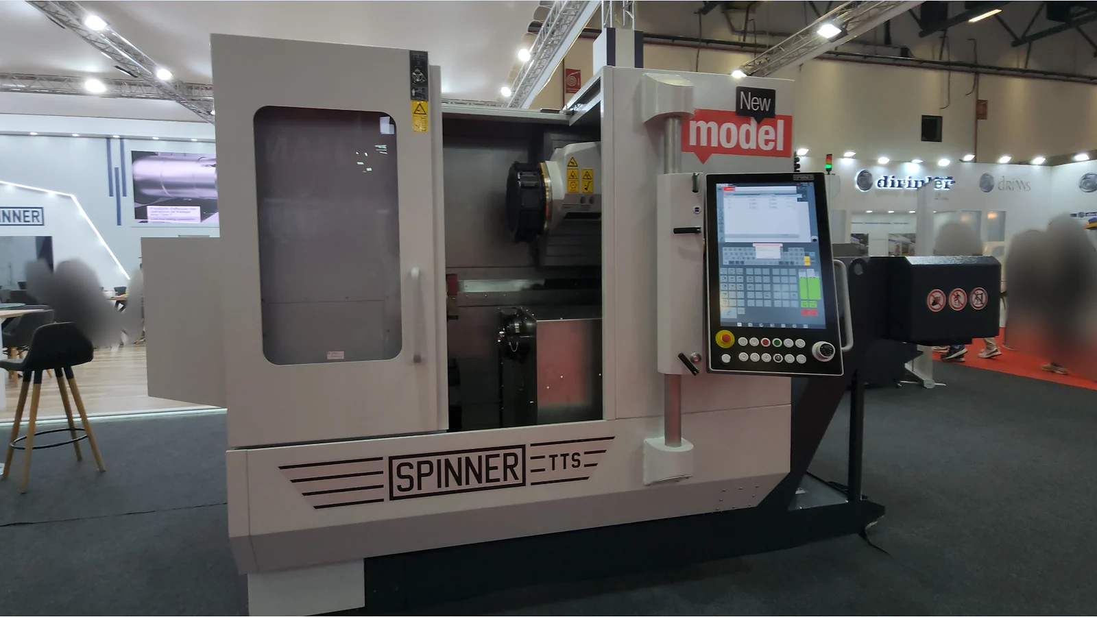
A lathe is a machine on which the workpiece rotates while a stationary cutting tool is fed into it to remove material. Cylindrical parts, shafts, bushings, flanges and threads are made on a lathe. On a conventional (manual) lathe the operator moves the slides with handwheels.
What is a CNC lathe?
A CNC lathe works on the same principle, but its X and Z axes are driven by servo motors under program control. Several tools are carried on a turret and changed automatically inside the program. Spindle speed, feed and coolant are all controlled by the program. Roughing, facing, grooving, drilling and threading can each be defined in a single block with a canned cycle; the most used of these is the G71 rough turning cycle. Add a C axis, live tooling, a Y axis and a sub-spindle and the CNC lathe becomes the mill-turn center described above. To learn the CNC lathe step by step, starting from machine anatomy, CNC Lathe Training Lesson 1 is the place to start.
What is a CNC mill or vertical machining center?
On a mill the roles are reversed: the cutting tool rotates and the workpiece is clamped to the table. A CNC mill, usually called a vertical machining center (VMC), moves in X, Y and Z, carries its tools in a tool magazine and swaps them with an automatic tool changer (ATC). Flat faces, pockets, slots, hole patterns, mold surfaces and 3D forms are milled. 4-axis machines with a rotary table, horizontal machining centers (HMC) and 5-axis machines are the advanced members of the same family. For an introduction to milling, see CNC Milling Training Lesson 1.
| CNC Lathe | CNC Mill / Machining Center | |
|---|---|---|
| Rotating element | Workpiece | Cutting tool |
| Basic axes | X, Z | X, Y, Z |
| Additional axes | C, Y, sub-spindle | A/B (rotary, tilting table), C |
| Tool carrier | Turret | Tool magazine + ATC |
| Typical parts | Shafts, bushings, flanges, threaded parts | Housings, plates, molds, hole patterns |
| Typical cycles | G71, G72, G76, G92 | G81, G83, G84, pocket cycles |
Types of CNC Machines
The main types of CNC machine tool used in metal cutting are:
- CNC lathe: 2-axis; versions with a C axis and live tooling; turning centers with a Y axis and sub-spindle; Swiss-type (sliding headstock) lathes.
- Vertical machining center (VMC): 3-axis; 4-axis with a rotary table; 3+2 and simultaneous 5-axis versions.
- Horizontal machining center (HMC): with pallet changer, for housings and prismatic parts; most are 4-axis.
- Gantry (portal) machining center: for large molds and aerospace parts.
- CNC grinding: cylindrical, surface and profile grinding.
- Wire EDM and sinker EDM: mold work in hardened steel.
- CNC drilling and tapping centers: fast machines for high-volume hole work.
Outside metal cutting, CNC laser and plasma cutting, press brakes, tube benders, woodworking routers and additive manufacturing all run under numerical control; they are outside the scope of this article.
CNC Controllers
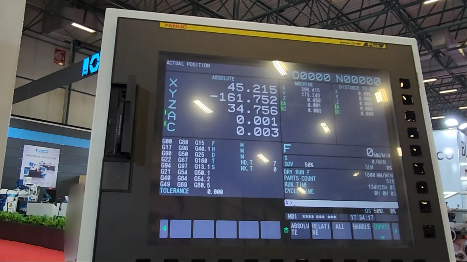
The controller is the machine’s computer, and it is usually made by a different company from the machine builder. The common brands are FANUC, Siemens SINUMERIK, Mitsubishi, Heidenhain, Haas (on its own machines) and Mazatrol (Mazak). The basic G and M codes are largely common, but the syntax of canned cycles, the parameters, the screens and the alarm numbers differ from brand to brand. A program that runs correctly on one control may not run unchanged on another, so programs must always be checked against the manual of the control in question. We compared which control suits which kind of work in the CNC control unit selection guide.
A Short Introduction to G and M Codes
A CNC program is made of blocks (lines). Each block contains address letters and numbers:
- G codes define how a motion is made: G00 rapid positioning, G01 linear cutting feed, G02/G03 circular interpolation, G90/G91 absolute or incremental mode, G54–G59 work offsets.
- M codes control machine functions: M03 spindle on clockwise, M05 spindle stop, M08/M09 coolant on/off, M06 tool change, M30 program end.
- Other addresses: X, Y, Z coordinates; F feed rate; S spindle speed; T tool; N block number.
O0001 (SAMPLE BLOCK)
N10 G21 G90 G40 G80
N20 T0101 M03 S1200
N30 G00 X52.0 Z2.0
N40 G01 Z-30.0 F0.25
N50 G00 X100.0 Z100.0 M05
N60 M30
This example only shows the structure. Before it is run on a real machine it must be adapted to the control, the tooling and the part dimensions, and proven in simulation.
Where Is CNC Used?
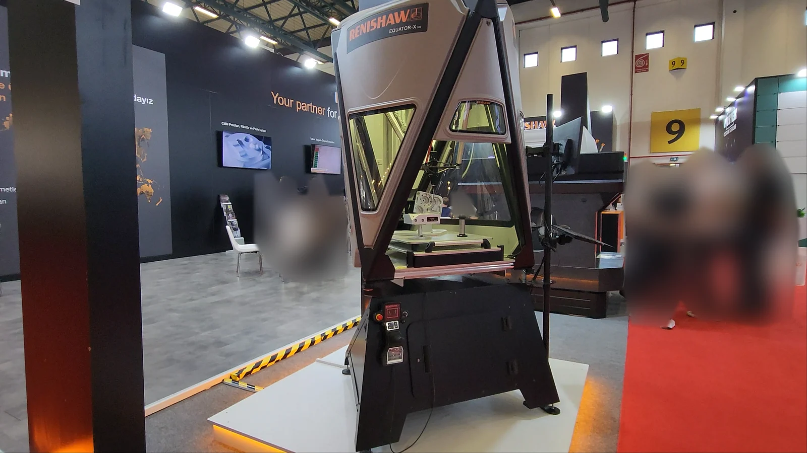
CNC technology is not limited to turning, milling, drilling and grinding. Wire and sinker EDM, laser and plasma cutting, presses and press brakes, welding robots, woodworking routers, coordinate measuring machines and additive manufacturing all run under numerical control. Defense, aerospace, automotive, mold and die, medical, energy and general machine building are the main user industries. In defense and aerospace, 5-axis machining is close to mandatory; in automotive supply, 4-axis VMCs and multi-turret lathes lead for series production.
Advantages and Limits of CNC
Advantages: once the program is proven, the second, tenth and thousandth part come out to the same size. Complex profiles and 3D surfaces are machined with an accuracy a manual machine cannot reach. Setup times are short; changing from one part to another means calling a program and swapping the fixture. Because speed and feed are constant and correct, tool life is more predictable. Cycle time is known in advance, which makes production planning easier. On 4- and 5-axis machines fewer setups also mean fewer setup-related dimensional errors.
Limits: the initial investment and maintenance cost are far higher than for a manual machine; on 5-axis machines both the investment and the need for CAM and operator skill rise further. Quality cutting tools and qualified people are required. For one-off or very simple jobs, programming and setup can take longer than machining the part by hand. A program error leads to expensive crashes, which is why graphic simulation, single-block mode and a slow first run at reduced feed are habits no shop can skip.
CNC Operator and CNC Programmer
The CNC operator prepares the machine: clamps the part, measures the tools, sets the work offsets, runs the program, measures the first part and corrects the offsets. The CNC programmer writes the program from the engineering drawing and generates toolpaths in CAM software. In small shops both roles sit with one person. The shared foundation for both is reading engineering drawings, the coordinate system, cutting parameters and the G and M codes of the control in use.
Frequently Asked Questions
What does CNC stand for? Computer Numerical Control.
What does CNC mean? It means a machine tool whose motions are controlled by a program of numbers, run by a computer built into the machine, rather than by an operator turning handwheels.
Are NC and CNC the same thing? No. NC is the first generation, driven from punched tape with no memory; CNC is the current system with a computer and memory inside the control.
When was the first CNC machine built? The first numerically controlled (NC) machine tool was demonstrated at MIT in 1952. Computer control (CNC) spread in the 1970s with the microprocessor.
What do 3-axis, 4-axis and 5-axis CNC mean? 3-axis means linear motion in X, Y and Z; 4-axis adds one rotary axis (a rotary table or indexer); 5-axis adds two rotary axes. In 3+2 (positional) machining the rotary axes are locked during the cut; in simultaneous 5-axis machining they move during the cut.
What is the main difference between a CNC lathe and a CNC mill? On a lathe the part rotates and the tool is stationary; on a mill the tool rotates and the part is clamped to the table. A lathe works in X and Z, a mill in X, Y and Z.
Where should I start learning CNC? With reading engineering drawings and the coordinate system. Then move on to CNC lathe or CNC milling training depending on your machine, and from there to G and M codes and canned cycles.
What language is a CNC program written in? An ISO-based language of G and M codes. Conversational alternatives exist, such as ShopMill/ShopTurn on Siemens and Mazatrol on Mazak.
Safety Notice and Disclaimer
CNC machines contain parts rotating at high speed and moving axes. Program and parameter changes produce physical motion; every new program should be checked first in graphic simulation, then in single-block mode at reduced feed. The manuals of the machine builder and the control manufacturer always take precedence. The information in this article is for educational purposes; Mentor CNC accepts no liability for direct or indirect damage arising from its use.