
Estimated reading time: 8 minutes
When you step up to a CNC machine, the screen and keypad in front of you usually do not belong to the company that built the machine. In most cases they belong to a separate control manufacturer. FANUC is one of the control brands you are most likely to meet on a shop floor.
This page explains what a FANUC control unit is, which series are used where, and which concepts should come first when you start learning FANUC. It does not teach a specific key or code; the goal here is to draw the map.
What Is a FANUC Control Unit?
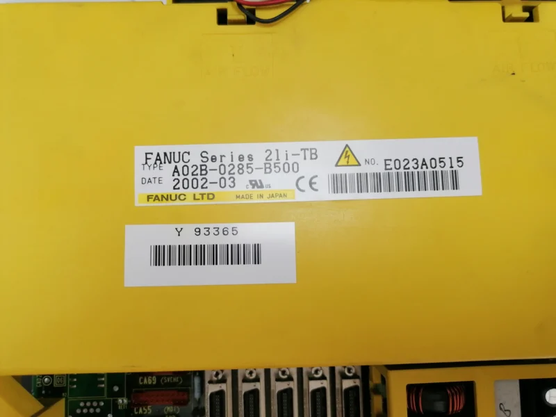
The FANUC control unit is the system that reads the CNC program, manages axis and spindle motion, stores tool and workpiece offsets, and reports machine status to the operator.
In short, a FANUC control does the following:
- Reads and interprets program blocks in sequence.
- Processes G, M, S, T and F commands.
- Sends motion commands to the servo and spindle drives.
- Displays position, offset, alarm and operating status on the screen.
- Evaluates commands coming from the machine operator panel.
- Handles program and data input/output operations.
Put simply, the control unit is the bridge between the program and the physical motion of the machine.
The Control Manufacturer and the Machine Tool Builder Are Not the Same
This is the single most important idea to grasp when learning FANUC. Most of the confusion you see on the shop floor comes from not knowing this distinction.
| Defined by FANUC | Defined by the machine tool builder |
|---|---|
| Screen groups (POS, PROG, OFFSET/SETTING, SYSTEM, MESSAGE) | Layout and key appearance of the operator panel |
| MDI keyboard and basic editing keys | Chuck, tailstock, turret, magazine and door functions |
| Standard G codes and canned cycles | The M code numbers that call those functions |
| Structure of the offset tables | Safety interlocks and PMC logic |
| Alarm numbers and CNC alarms | Machine-specific alarms and operator messages |
| Reference return logic | Reference direction and axis sequence |
The practical consequences of this table are:
- Two machines using the same FANUC 0i control may have operator panels that look nothing alike.
- An M code that clamps the chuck on one machine may do something entirely different on another.
- The FANUC alarm manual explains CNC alarms; for a machine-specific alarm you need the machine builder’s manual.
- “This is how it is done on FANUC” is not always transferable. What is transferable is the screen logic of the control itself.
Three Characteristics That Stand Out When Learning FANUC
1. G code systems A, B and C on lathes
FANUC lathe controls can use three different G code systems. The task of a G code with the same number can change between systems.
The best known example is the maximum spindle speed limit: in G code system A this is usually done with G50, while in other systems G92 can take on the same job.
For that reason a program taken from another FANUC lathe should never be assumed compatible simply because the control brand is the same.
2. The letters T and M in the model name
T: Lathe type controlM: Milling or machining centre type control
For example, a FANUC 0i-TC is a lathe control while a FANUC 0i-MB is a machining centre control. The difference is not only in the name: the structure of the offset tables, the canned cycles and the meaning of some G codes change as well.
A concrete example: on a milling control G98 and G99 select the return plane of a canned cycle, while on a lathe using G code system A they relate to the feed mode. Same number, different job.
3. Offsets are kept in separate tables
FANUC stores tool data and workpiece position in separate tables. On a lathe these are Geometry and Wear; on a mill the tool length (H), cutter radius (D) and work offset (G54-G59) tables are independent of each other.
This structure provides flexibility but also brings a responsibility: the operator has to keep track of which row in which table is active. If the number called by the program does not match the value entered in the table, the tool will go to the wrong place even though the program itself is correct.
FANUC Series Map
The FANUC controls you are likely to meet in a workshop can be grouped roughly into three generations.
| Generation | Lathe | Mill / machining centre | Typical characteristic |
|---|---|---|---|
| Older generation | 0-T, 0-TC | 0-M | Plain screen, mostly physical keys, RS-232 |
| Middle generation | 16T, 18T, 21T | 16M, 18M, 21M | Advanced soft keys, Memory Card |
| 0i family | 0i-T, 0i-TC, 0i-TF, 0i-TF Plus | 0i-M, 0i-MB, 0i-MF, 0i-MF Plus | Colour LCD, advanced graphics, USB and network on newer versions |
The extra letters in a model name indicate the generation or model group of the control. However, you cannot tell every capability of a machine from the model name alone. The FANUC options that were purchased and the machine builder’s configuration are what actually decide.
One example: the presence of a USB slot on the panel does not mean that program transfer over USB is enabled and configured on that control.
Five Screens You Will Meet on Every FANUC Control
Even when the series changes, the screen groups stay largely the same. An operator meeting a new FANUC control for the first time only needs to recognise these five screens.
| Key | What does it show? | When is it used? |
|---|---|---|
POS | Axis positions (ABS, REL, ALL) | Manual motion, approaching with a tool, watching the program |
PROG | Program content and program list | Writing, searching, editing and checking a program |
OFFSET/SETTING | Tool and workpiece offsets, settings | Tool measuring, setting part zero, wear correction |
SYSTEM | Parameters and basic diagnostic data | Mostly maintenance; read-only at operator level |
MESSAGE | Alarms, alarm history, operator messages | The first screen to check when the machine stops |
A sixth key, GRAPH or CUSTOM/GRAPH, may sit next to these five; the graphics and tool path screens are opened from there.
Where Should You Start Learning FANUC?
For a beginner operator the most productive order starts with getting to know the control, not with memorising codes. The order followed in the Mentor CNC FANUC training set is:
- Control unit, screen and panels — telling the CNC screen, the MDI keyboard and the machine operator panel apart
- Operating modes — EDIT, MEMORY/AUTO, MDI, JOG, HANDLE, REF/ZRN
- Reference return and position screens — ABS, REL, ALL and manual motion
- Program management — O numbers, searching, INSERT, ALTER, DELETE
- Automatic operation — Cycle Start, Feed Hold, Single Block, Optional Stop, Override
- Offset systems — Geometry/Wear on a lathe, H, D and G54-G59 on a mill
- G/M codes and cycle checking — modal states, G96/G97, G70-G76, G81-G89
- Alarm and diagnosis screens — reading alarms, alarm history, the operator/service boundary
- Program transfer and backup — I/O Channel, RS-232, Memory Card, USB, DNC
- Graphics, Dry Run and restart — verifying a program safely
The logic of this order is: first you learn to read where you are, then to control what you are doing, and finally to verify the program.
Frequently Asked Questions
Can an operator who learned FANUC use another brand of control?
Key names and screen layouts change, but the basic operating logic is similar regardless of brand: select a mode, call the program, enter the offsets, start under control. An operator who has built that logic on FANUC adapts to other controls more quickly.
Is it still useful to learn an old FANUC 0-T today?
Yes. The screens of older controls are plain, but the concepts are the same: O numbers, Geometry/Wear, reference return, modal G codes. On top of that, these controls are still widely running in industry.
Can I send a FANUC program straight to another FANUC machine?
It should not be assumed compatible. The G code system, the cycle format, the tool offset structure and especially the M codes can differ between two machines. After the program is transferred its content should be checked from beginning to end and tried out under control.
Can an operator change parameters?
Not at beginner level. Parameters, PMC/Ladder, servo and spindle settings, APZ/APC and reference parameters are maintenance or service matters. An operator may view these screens but should not write values into them.
Short Summary
- The FANUC control unit is the bridge between the program and the motion of the machine.
- The control manufacturer and the machine builder have separate responsibilities; M codes and panel layout belong to the machine.
- Lathe controls may use G code system A, B or C; the same number can carry a different job.
- The
Tin a model name indicates a lathe control,Ma mill or machining centre control. - Offsets are kept in separate tables; following the active row is the operator’s responsibility.
- Even when the series changes, the POS, PROG, OFFSET/SETTING, SYSTEM and MESSAGE screens are common.
- A slot being present on the panel does not mean the related function is enabled.
Screen layout, key names and some functions may differ according to the FANUC control series and the machine builder’s configuration. Always take the operating manual of your own FANUC control and machine as the reference.