
Estimated reading time: 6 minutes
What Will You Learn in This Lesson?
In this lesson you will learn the basic operating modes found on CNC machines with a FANUC control:
- EDIT
- MEMORY / AUTO
- MDI
- JOG
- HANDLE
- REF / ZRN
You will also learn which operation should be carried out in which mode, and the problems that selecting the wrong mode can cause.
The basic operating logic of these modes is largely common to FANUC lathe and vertical machining center controls.
What Is a FANUC Operating Mode?
The operating mode determines which operation the operator can carry out on the control unit.
For example:
EDITto edit a program,MEMORY/AUTOto run a stored program,MDIto apply a short command directly,JOGto move an axis manually and continuously,HANDLEto move an axis precisely with the handwheel,REF/ZRNto send the machine to its reference position.
When the wrong operating mode is selected, the key you press or the command you give may not produce the expected result. If a program is visible on the screen but cannot be edited, or if the program does not start when the Cycle Start button is pressed, one of the first things to check is the active operating mode.
Where Is the Operating Mode Selected?
Operating modes are generally selected from the machine operator panel.
Depending on the machine, one of the following methods may be used:
- Rotary mode selector switch
- Separate mode buttons
- Membrane keypad
- On-screen machine operator panel
- Physical and software selections used together
The active mode is mostly also shown in the status area of the CNC screen. Expressions such as EDIT, MEM, MDI, JOG, HND or REF may be seen on the screen.
Even if the FANUC control unit is the same, the appearance of the mode selection panel may differ according to the machine tool builder.

1. EDIT Mode
EDIT is the operating mode in which the programs in the CNC memory are created and edited.
In this mode, in general:
- A new program can be created.
- An existing program can be opened.
- A program line can be added.
- A command can be changed.
- A word or a block can be deleted.
- A program can be searched for, copied or deleted.
- With the appropriate connection settings, program transfer can be carried out.
The basic keys used in program editing are:
INSERTALTERDELETEEOB- Cursor and page keys
Why can a program not be changed in EDIT mode?
If the program cannot be changed even though the control is in EDIT mode, the following situations should be checked:
- The program protect switch may be in the protected (locked) position. While protection is active the program can be displayed but not edited.
- The selected program may be a protected program.
- The control unit may be in a state that does not allow editing.
- The cursor may not be on the correct word or block.
- The key being used may not be suitable for the operation.
Common mistake: seeing the program on the screen does not mean the program is open for editing. A program can also be displayed in MEMORY/AUTO mode, but EDIT mode is required for normal editing operations.
Searching for, creating and editing programs will be explained in detail in Lesson 4.
2. MEMORY / AUTO Mode
This is the mode used to run a program stored in the FANUC control memory automatically.
On older controls this mode is mostly shown as MEM or MEMORY, and on some machine panels as AUTO. Even if the name differs, the basic purpose is the same: to run the selected program in the CNC memory.
In MEMORY/AUTO mode:
- The selected program can be started with Cycle Start.
- The program blocks are executed in order.
- The active block and sequence number can be followed on the screen.
- Operator controls such as Single Block, Optional Stop and Block Skip can be used.
- The permitted speed percentages can be set with Feed Override and Rapid Override.
- The program can be held with Feed Hold.
Selecting MEMORY/AUTO mode alone is not enough before starting the program. The selected program, the start block, the active offsets and the machine conditions must also be checked.
Caution: always verify which program is selected before pressing the Cycle Start button. A different program left over from the previous job may still be active in the memory.
Automatic operation and operator controls will be covered in detail in Lesson 5.
3. MDI Mode
MDI stands for “Manual Data Input”.
In this mode the operator can enter and run a short command or a limited number of program blocks directly. The command entered is generally not used as a permanent production program.
The blocks entered in MDI are written into a temporary program area; on most FANUC controls this area appears with the number O0000. This area is cleared when RESET is applied or the power is switched off. In other words, an MDI entry does not become a permanent program.
Common uses of MDI mode:
- Giving the spindle a particular speed command
- Starting or stopping the spindle
- Calling a tool
- Indexing the turret
- Giving a tool change command on a milling machine
- Running an auxiliary function
- Sending an axis to a particular coordinate
- Applying a short one-off check command
An example MDI line may look like this:
S800 M03;When the appropriate machine conditions are met, this command gives the spindle a speed and direction of rotation command.
However, execution of the command may depend on the door, chuck, lubrication, emergency stop and other machine safety conditions.
Points to watch when using MDI
Before entering an MDI command:
- The current axis positions should be checked.
- It should be understood which axis or machine function the command will affect.
- The active G codes and offsets should be taken into account.
- The command should be read again on the screen.
- The Cycle Start button should be pressed in a controlled way.
Common mistake: thinking of MDI mode as a harmless trial area. Commands given in MDI can produce real machine movement or a real auxiliary function.
MDI should not be confused with EDIT mode, which is used to edit programs. In EDIT mode a program in the memory is changed, while in MDI mode the command entered is prepared to be applied directly.
The five most common MDI jobs: example lines
General flow: mode switch to MDI → PROG key (on the 0i series the MDI screen sits under this key) → type the line → EOB → INSERT → CYCLE START. The line is cleared by RESET or by switching the power off. The examples below are for a vertical machining center; M-code numbers and safety interlocks vary between machine builders.
- Tool change:
T02 M06;— Z must be at reference first (G91 G28 Z0;), the part and fixture must be clear of the tool-change path, and pocket 2 of the magazine must really hold that tool. - Starting and stopping the spindle:
S800 M03;— stop withM05;. The door must be closed; make sure the tool holder is clamped in the spindle. - Reference return: first
G91 G28 Z0;, thenG91 G28 X0 Y0;. G91 is modal: do not forgetG90;when you are done. The same job can be done in ZERO RETURN mode with the axis keys. - Checking the part zero: with the tool at a safe height,
G90 G54 G00 X0 Y0;— the tool centre must stop exactly over the part zero. Never give Z a blind command from MDI. - Indexing the turret on a lathe:
T0303;— with the turret clear of the part and the tailstock.
A command typed in MDI runs the moment you press start; there is no single-block preview as in AUTO mode. Read the line on the screen once more before sending it, keep the Rapid Override low, and do not leave the mode switch in MDI when you are finished.
4. JOG Mode
JOG is the mode in which the axes are moved manually using the direction keys on the operator panel.
In general the operator:
- Selects JOG mode.
- Determines the axis to be moved.
- Presses the appropriate direction key.
- The axis moves as long as the key is held down.
- The movement stops when the key is released.
On a lathe control mostly X and Z are used; on a vertical machining center the X, Y and Z axes are used. On machines with additional axes, other selections may also be seen.
The JOG movement speed may be affected by the JOG Feed or Feed Override control on the panel. On some panels there is also a Rapid Traverse button for manual rapid movement.
Caution: verify the axis direction of the machine before pressing a direction key. The direction of movement on the machine may be perceived differently at first glance because of the angle from which the operator is looking.
Moving an axis with JOG will be explained in detail in Lesson 3.
5. HANDLE Mode
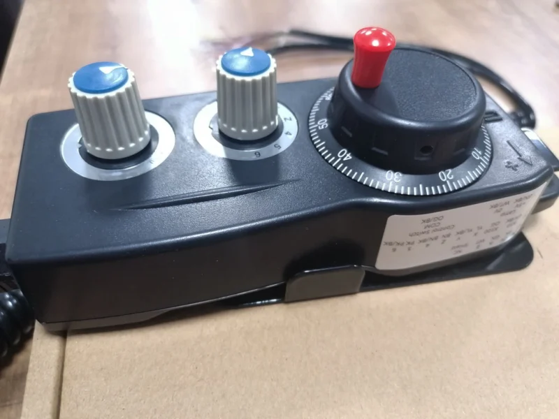
HANDLE mode is used to move the axes precisely using the manual handwheel, that is the MPG.
The operator:
- Selects the axis to be moved.
- Determines the handwheel step.
- Turns the handwheel in the appropriate direction.
- Follows the axis movement on the position screen.
The common handwheel steps are:
×1×10×100
These steps mostly mean 0.001 mm, 0.01 mm and 0.1 mm of movement per pulse. However, the real amount of movement depends on the input unit of the control and the machine configuration; the value should be verified from the manual of your own machine.
On some machines different step names or movement amounts may be used. The larger the step, the greater the movement produced by each pulse of the handwheel.
HANDLE mode is generally used to:
- bring the tool up to the workpiece in a controlled way,
- measure a tool,
- set the workpiece zero,
- carry out precise positioning.
Common mistake: moving without checking the handwheel step. If the operator expects ×1 but ×100 is selected, the tool may travel much further than expected.
Using HANDLE together with the position screens will be shown in detail in Lesson 3.
6. REF / ZRN Mode
REF, ZRN or ZERO RETURN is the mode used to send the axes to the defined reference position of the machine.
This operation allows the control unit to recognize the machine position correctly. Especially on systems that require a reference return, the axes may need to be sent to the reference position after the power is switched on.
The general procedure is as follows:
- REF/ZRN mode is selected.
- The relevant axis is determined.
- The reference return direction key is pressed.
- The axis moves until it reaches the reference position.
- The reference indicator and the position screen are checked.
The reference return order and the direction of movement may differ from machine to machine. On some machines the Z axis may need to be brought to a safe position first. On some systems with absolute position encoders, the classic reference return operation may not be needed at every power-on.
For this reason the reference return operation should not be applied with a single memorized axis order.
Caution: if the tool is close to the workpiece, chuck, fixture or table, there may be a risk of collision during the reference return. Do not send the axes to reference without checking the path of movement.
The REF/ZRN operation and the position screens are among the main subjects of Lesson 3.
A Short Comparison of the Modes
| Operation to be carried out | Mode to be used |
|---|---|
| Editing a program in the memory | EDIT |
| Running a stored program | MEMORY/AUTO |
| Applying a short command directly | MDI |
| Moving an axis with a direction key | JOG |
| Moving an axis precisely with the handwheel | HANDLE |
| Sending an axis to the machine reference | REF/ZRN |
This table shows the general operating logic. Some special operations may require a different mode or additional selections.
FANUC Note
On older FANUC Series 0, 16, 18 and 21 controls, the mode names may be written next to the physical selector switch. On newer controls such as FANUC 0i-TC, 0i-MB, 0i-TF and 0i-MF, separate mode buttons or an operator panel prepared by the machine tool builder may be used.
Expressions such as MEMORY and AUTO, REF and ZRN, or HANDLE and HND are mostly different names for the same basic operating mode.
The screen layout, key names or some functions may differ according to the FANUC control series and the configuration of the machine tool builder. Check the operation manual of your own FANUC control and machine.
Short Summary
- EDIT is for creating and editing the programs in the memory.
- MEMORY/AUTO allows the selected program to be run automatically.
- MDI is used to enter and apply short commands directly.
- JOG moves the axes manually with the direction keys.
- HANDLE provides precise manual movement with the handwheel.
- REF/ZRN sends the axes to the reference position of the machine.
- If an operation does not work, the active operating mode should be checked first.
- Mode names and the selection panel may differ according to the FANUC series and the machine tool builder.
Test Yourself
- In which mode is a program held in the memory edited?
- Which basic form of operation do the expressions MEMORY and AUTO indicate?
- What is the basic difference between MDI and EDIT?
- In what way do the JOG and HANDLE modes differ from each other?
- Why should the handwheel step be checked before moving?
- What is the task of the REF/ZRN mode?
- Why should the reference return order not be assumed to be the same on every machine?
- If the program does not start when the Cycle Start button is pressed, which information should be checked first?