
Estimated reading time: 7 minutes
What Will You Learn in This Lesson?
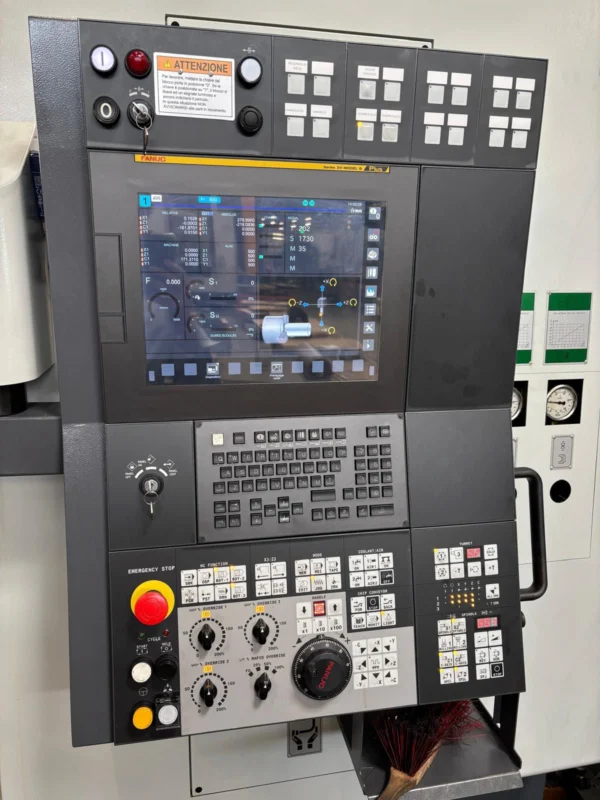
In this final lesson you will learn:
- the FANUC graphics and tool path screens,
- the checks to be made before running a program,
- the use of Single Block and Dry Run,
- restarting the program from a particular point,
- the importance of the modal states during a restart,
- the basic differences in use between older and newer FANUC series.
The aim is to check the program on the FANUC control safely and systematically. Using graphics or Dry Run does not mean that the program is automatically correct and collision-free.
The FANUC Graphics Screen
The graphics screen draws the programmed tool path on the control screen and allows the operator to inspect it visually.
Depending on the control series, this screen can be reached from the following keys or menus:
GRAPHCUSTOM/GRAPHPROGRAM CHECKTRACESIMULATIONANIMATION
The main options that may be found on the graphics screen:
- Selecting the program to be displayed
- Starting and stopping the drawing
- Clearing the screen
- Zooming in and out
- Moving the display area
- Setting the drawing scale
- Following the tool path
- Displaying the turning profile
- Opening the selected plane or a three-dimensional view on a milling machine
On older controls such as FANUC 0-T and 0-M the graphics may be simpler. On the FANUC 16/18/21 and 0i series there may be more advanced soft keys, a coloured tool path or a part shape display.
What Does the Graphics Screen Help You Check?
The graphics screen can help you notice the following errors:
- An unexpected direction of movement
- A wrong profile or hole position
- A missing program block
- An incorrect arc direction
- A cycle calling the wrong profile blocks
- The program producing movement in an unexpected area
- A position difference caused by the G54-G59 selection
- A turning cycle following the wrong X-Z profile
Graphics is particularly useful after a change has been made to the program. Not only the changed line itself but also the path it forms together with the preceding and following movements should be examined.
The Limits of the Graphics Screen
The graphics screen is an important checking tool, but it does not give a real guarantee against collision.
Depending on the control and the available options, the graphics:
- may not show the real tool holder,
- may not show the chuck, turret, tailstock or workholding elements,
- may not take the vice, the fixture and the clamps into account,
- may not use the real tool overhang length,
- may not show the physical result of M codes specific to the machine tool builder,
- may not fully reflect an offset or tool data error,
- may show subprograms, macros or special cycles in a limited way,
- may draw the program path but not simulate the real machine dynamics.
Caution: not seeing a collision in the graphics does not mean there will be no collision on the real machine. Graphics is only one of the checks alongside program, offset, tool, workholding and controlled operation.
The General Procedure for a Graphics Check
Even though the key names may differ from control to control, the general order of operation is as follows:
- Call the correct O program.
- Verify that the required subprograms are in the memory.
- Open the graphics or program check screen.
- Select the suitable display plane for turning or milling.
- If necessary, set the drawing area and the scale.
- Clear the old tool path from the screen.
- Start the drawing from the beginning of the program.
- Examine the tool path, the cycles and the retract movements.
- Zoom in on suspicious areas.
- Verify the active program again after the graphics is complete.
When you leave the graphics screen, it should be checked which block or mode the program is left in.
The Final Check Before Running a Program
A program opening on the screen without an alarm does not show that it is ready for production.
Before Cycle Start, these five areas should be checked together:
1. The program
- Is the correct O program selected?
- Is the beginning of the program correct?
- Are the subprograms in the memory?
- Have the edited lines been read again?
- Is there a suitable ending command at the end of the program?
2. Coordinates and offsets
- Is the correct Geometry and Wear row being used on the lathe?
- Are the H and D numbers correct on the milling machine?
- Is the G54-G59 row called by the program the same as the measured work zero?
- Is there an unexpectedly large value in the offsets?
- Are the decimal points and the value signs correct?
3. Tool and machine conditions
- Is the tool in the program physically in the correct position?
- Is the turret or magazine information correct?
- Are the tool length and the overhang safe?
- Are the part, the chuck, the vice and the fixture clamped correctly?
- Are the door and the other safety conditions satisfied?
4. Programmed working states
- Are the active G codes correct?
- Have G96/G97 and the maximum speed limit been checked in the turning program?
- Is the correct Work Offset and H offset selected in the milling program?
- Are the S, F, T, H and D values correct?
- Are the Optional Stop and Block Skip selections consistent with the program?
5. The operator panel
- Is MEMORY/AUTO mode selected?
- Is Single Block on where required?
- Is the Feed Override at a suitable value?
- Is the Rapid Override at a low and controlled starting value?
- Is there an alarm or an operator message on the screen?
- Is the direction and target of the first movement understood?
Checking a Program with Single Block
As we learned in Lesson 5, Single Block allows the program to be executed block by block.
General use on the first run:
- Switch Single Block on.
- Set the Rapid Override to a low value.
- Bring the Feed Override to a suitable level.
- Open the position or program check screen.
- Read the whole of the next block.
- Press Cycle Start once.
- Watch the movement and the position on the screen.
- Read the new block again before the next Cycle Start.
Even with Single Block on, a cycle or a machine-specific function can execute more than one movement within a single block. It should not be assumed that tool change, turret indexing or cycle movements will stop separately at every step.
What Is Dry Run?
Dry Run is an operator function that helps to execute the movements of the program with a different feed behaviour for checking purposes.
It may be found on the panel under the following names:
DRY RUNDRNTEST- another name determined by the machine tool builder
While Dry Run is on, the programmed feed movements may be executed at a test speed set from the operator panel, according to the configuration of the control and the machine.
The critical point about Dry Run
Dry Run is not only a virtual simulation carried out on the screen. Depending on how the function is applied, the axes may move for real.
For this reason:
- It should be verified that the tool and the part are safe.
- The effect of Rapid Override and Feed Override should be understood.
- It should be taken into account that the spindle and auxiliary functions may run.
- The door and safety procedures should be applied.
- The operator should watch the movement area continuously.
Common mistake: thinking that the machine will not move when Dry Run is selected. Dry Run is a program checking method that can produce real axis movement.
Which movements and cycles Dry Run affects may differ according to the machine tool builder. The function may be limited in threading, rigid tapping and synchronised movements in particular.
Machine Lock and Dry Run Are Not the Same
On some FANUC panels there may be a MACHINE LOCK or a similar test option.
While Machine Lock is on, the CNC coordinates may change as if the program were running while the physical axis movements are prevented. However:
- Auxiliary M functions may be executed.
- The spindle or the coolant may run.
- The position on the control screen and the physical machine position may become different.
- After Machine Lock is switched off, the coordinate state should be evaluated carefully.
Machine Lock is not a general safety method that replaces Dry Run or the graphics screen. It should not be used without the builder’s procedure.
Why Is a Program Restarted?
Restarting a program from the middle may be needed in the following situations:
- A long wait after Feed Hold
- RESET being applied
- The cycle being interrupted by an alarm
- A tool change
- A dimensional check
- A power or connection interruption
- A particular operation being repeated
However, bringing the program to a particular N block on the screen and pressing Cycle Start is not by itself a safe restart.
Sequence Number Search Is Not the Same as a Safe Start
For example, the N500 line can be searched for in the program:
N500 G01 X... Z... F...;The control can bring the cursor to this line. However, the following information activated before N500 may be missing:
- The active G54-G59 system
- The tool and offset number
- The G43 tool length compensation
- G41/G42 or the tool nose radius compensation
- The G96/G97 spindle mode
- The maximum spindle speed limit
- The spindle direction and speed
- The feed mode
- The cycle mode
- The coolant
- The plane and unit selection
- The subprogram or macro state
A sequence number search only finds a position in the program; it should not be assumed that it automatically applies the preceding blocks safely.
The FANUC Program Restart Function
On some FANUC controls there may be special restart functions such as PROGRAM RESTART, RESTART, P TYPE or Q TYPE.
Depending on the control series and the option, these functions may:
- scan the program up to the specified sequence number,
- collect the necessary modal information,
- show the restart position,
- help to bring the tool to the starting point,
- allow the program to continue from a particular block.
However, the control scanning the program does not guarantee that the physical tool is in the correct and safe position.
The restart operation requires the following to be verified separately:
- The active tool
- The active offset
- The workpiece coordinate
- The physical position of the axes
- The spindle state
- The auxiliary functions
- The interruption point within the cycle
- The approach path of the tool to the part
Safe Restart Checklist
Before the program is restarted:
- Determine the cause of the alarm or the stop.
- Record at which block the program was interrupted.
- Check the physical position of the tool and the axes.
- Determine which operations on the part have been completed.
- Examine the blocks that would be dangerous to execute again.
- Verify the correct tool and offset.
- Check the active Work Offset or the lathe zero.
- Re-establish the necessary modal G codes.
- Verify the state of the spindle and the auxiliary functions.
- Determine a safe approach position.
- If necessary, start the program from a suitable preparation block.
- Use Single Block and low percentage settings.
- Check Distance To Go and the target coordinate before the first movement.
- Do not continue haphazardly from the middle of an interrupted cycle.
Caution: restarting a program that was interrupted during threading, a drilling cycle, a roughing cycle, a subprogram or a macro requires special evaluation. Where necessary, the programmer or authorised technical personnel should be involved in the process.
Common Restart Mistakes
- Searching only for the N number and pressing Cycle Start
- Continuing the program while the wrong tool is active
- Not re-activating the G43 H offset
- Starting with the wrong G54-G59 system
- Not checking the speed limit while G96 is active
- Assuming that the coolant or spindle command is active
- Continuing from the middle of a cycle
- Executing a rapid movement command while the tool is inside the part
- Thinking that the modal states did not change after RESET
- Accepting the graphics screen as a guarantee against collision
Older and Newer FANUC Series
In FANUC control names you may meet letters showing the application area of the machine:
T: lathe type controlM: milling or machining centre type control
FANUC series that may be seen on lathes
- FANUC 0-T
- FANUC 0-TC
- FANUC 16T
- FANUC 18T
- FANUC 21T
- FANUC 0i-T
- FANUC 0i-TC
- FANUC 0i-TF
- FANUC 0i-TF Plus
Series that may be seen on milling machines and machining centres
- FANUC 0-M
- FANUC 16M
- FANUC 18M
- FANUC 21M
- FANUC 0i-M
- FANUC 0i-MB
- FANUC 0i-MF
- FANUC 0i-MF Plus
The additional letters in the model name may indicate the generation or the model group of the control. However, all the functions of the machine cannot be understood from the model name alone. The FANUC options purchased and the configuration of the machine tool builder are also important.
What Can Change Between Series?
- The size and colour structure of the screen
- The physical function keys
- The order of the soft keys
- The names of the program and file menus
- The graphics capabilities
- USB, Memory Card and network support
- The program memory
- The cycle options
- The program restart functions
- The G code system
- The appearance of the offset table
- The layout of the operator panel
What Stays Common in the Basic FANUC Logic?
Even when the series changes, the following basic approach is largely preserved:
- An operating mode is selected.
- Screen groups such as
POS,PROG,OFFSET/SETTING,SYSTEMandMESSAGEare used. - Programs are managed by the O number.
- Programs are edited in EDIT mode.
- Programs are run in MEMORY/AUTO mode.
- Short commands are entered with MDI.
- Manual movement is carried out with JOG and HANDLE.
- Reference return is applied with REF/ZRN.
- Cycle Start, Feed Hold and RESET are used.
- Alarm and position information is followed on the screen.
- Offsets are managed in separate tables.
An operator meeting a new FANUC control should focus first on this common operating logic rather than on the appearance of the keys.
FANUC Note
Even if the same FANUC control model is used on two different machines, the operator panels, the M codes, the safety interlocks and the turret or ATC behaviour may be different.
The screen layout, key names or some functions may differ according to the FANUC control series and the configuration of the machine tool builder. Check the operation manual of your own FANUC control and machine.
Short Summary
- The graphics screen helps to inspect the programmed tool path visually.
- Graphics does not guarantee that there will be no collision on the real machine.
- Single Block may not stop every physical movement separately.
- Dry Run is not a virtual simulation; it can produce real axis movement.
- Machine Lock and Dry Run are not the same function.
- Searching for a sequence number does not mean a safe program restart.
- On a restart, the tool, the offset, the coordinate and the modal G codes should be verified.
- Work should not continue haphazardly from the middle of a cycle.
- Even though the screens of older and newer FANUC controls differ, the basic operating logic is largely common.
- Machine-specific M codes and panel functions should be verified from the machine tool builder’s manual.
Test Yourself
- Which program errors can the graphics screen help you notice?
- Why is not seeing a collision in the graphics not a guarantee of safe operation?
- Is Dry Run only a simulation carried out on the screen?
- Why may Single Block not stop all the movements of a cycle separately?
- What is the basic difference between Machine Lock and Dry Run?
- Why does searching for a particular N number not by itself provide a safe restart?
- Which modal information should be checked on a restart?
- What kind of risk can arise if a milling program is started with the G43 H offset forgotten?
- What should be checked before a restart in a turning program using G96?
- Why does a program interrupted in the middle of a cycle require special evaluation?
- What do the letters T and M in FANUC model names generally indicate?
- What is the basic operating logic that stays common on older and newer FANUC controls?