
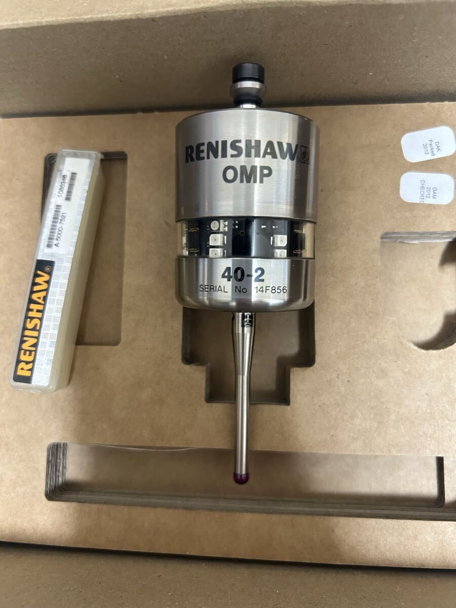
One of the most important auxiliary technologies that increase precision and productivity on CNC machines is the probing system. In this guide we cover probing systems step by step — from workpiece inspection probes to tool setting probes, from calibration macros to everyday usage tips.
The macro numbers and program examples in this article are based on the widely used Renishaw probe software running in Fanuc format (Inspection Plus and tool setting macros). Macro numbers, address letters and variable numbers can differ depending on the probe model, software version and the machine builder’s installation. Always check the manual of the probe software installed on your own machine before applying anything.
1. Introduction to Probing Systems
Manual zeroing and manual tool offset entry on CNC machines take time and are open to human error. By automating these operations, probing systems can — according to manufacturer data — reduce setup times by up to 80%, bring the error margin down to micron level, prevent scrap through broken tool detection, and eliminate secondary operations by measuring parts on the machine.
Today probes are used everywhere: from vertical machining centers to lathes, from die and mold shops to aerospace parts.
2. Main Components of a Probing System
- Probe: The touch-trigger device mounted in the machine spindle or on the table.
- Receiver / interface unit: The device that transmits probe signals to the CNC (for example OMI-2T, MI8, MI12).
- Signal transmission: Optical, radio or hard-wired.
- Macro programs: The CNC macros that manage probe measurements and update offsets.
3. Using the Workpiece Inspection Probe
The workpiece inspection probe automatically establishes the part origin in X, Y and Z. Compared with manual edge finding, this is much faster and more repeatable.
3.1. Checking the Skip Signal
To make sure the probing system works correctly, first test the skip signal. After the probe has been switched on with the relevant M code:
G91 G31 Z-150. F100This command moves the Z axis until the stylus touches a surface and stops at the moment of contact.
⚠️ Keep your hand on the emergency stop during this test. If the axis does not stop when the probe triggers, stop the motion immediately and check the wiring, the interface unit and the skip parameters. No probing cycle should be run before the skip signal has been verified.
3.2. Loading the Probe Macros
For the probe to work, the measurement macros must be loaded into the machine memory. The table below shows the typical program numbers found in the common Renishaw Inspection Plus package in Fanuc format:
| Macro No | Description |
|---|---|
| O9721 | X diameter move |
| O9722 | Y diameter move |
| O9723 | Active tool offset update |
| O9724 | Settings macro |
| O9726 | Basic X, Y, Z move |
| O9727 | Vector diameter move |
| O9731 | Vector calibration data |
| O9732 | Offset update |
| O9801 | Probe length calibration |
| O9802 | Stylus X, Y offset calibration |
| O9804 | Stylus ball radius calibration |
| O9810 | Protected positioning move |
| O9811 | Single surface measurement (X, Y, Z) |
| O9812 | Web / pocket measurement |
| O9814 | Bore / boss measurement |
| O9815 | Internal corner measurement |
| O9816 | External corner measurement |
| O9817 / O9818 | 4th axis measurement |
| O9821 | Angled surface measurement |
| O9823 | 3-point bore / boss measurement |
| O9834 | Feature-to-feature measurement |
| O9843 | X, Y plane angle measurement |
The macro list of your own version may differ from this table; refer to your software’s installation manual for the definitive list.
4. Calibration Procedures
Calibration is the first and most important step for guaranteeing probe accuracy. Measurements taken without calibration are not reliable.
4.1. Z Length Calibration
Purpose: To establish the probe’s length offset in the Z axis.
G65 P9801 Zz TtZz: The reference surface where the length measurement is taken (example: Z0)Tt: The offset number to update
O0001;
G17 G40 G49 G80;
G91 G28 Z0;
G90 G54 G0 X0 Y0;
M19;
G43 H1 Z150;
G65 P9810 Z10 F1000;   (protected approach)
G65 P9801 Z0 T1;       (calibration)
G65 P9810 Z100;
G91 G28 Z0;
M30;
When this program runs, tool offset number 1 is updated automatically. Note: in some software versions, length calibration uses the K address with the known reference height instead of Z and T; verify the format of your own version in its manual.
4.2. Stylus X and Y Offset Calibration
Purpose: To find the deviation of the stylus ball center from the spindle centerline in X and Y. A precision ring gauge is used for this.
G65 P9802 DdDd: The exact diameter of the ring gauge (mm)
O0002;
G17 G40 G49 G80;
G91 G28 Z0;
G90 G54 G0 X0 Y0;
M19;
G43 H1 Z150;
G65 P9810 Z-10 F1000;
G65 P9802 D50;
G65 P9810 Z100;
G91 G28 Z0;
M30;
In this installation the calibration results are written to macro variables 502 and 503. The more precisely you locate the center of the ring gauge, the more precisely the deviation between the probe center and the spindle center is measured. The variable numbers where calibration data is stored can change with the software version and the settings macro.
4.3. Stylus Ball Radius Calibration
Purpose: To determine the effective radius of the stylus ball in the X and Y directions.
G65 P9804 DdO0003;
G17 G40 G49 G80;
G90 G54 G0 X0 Y0;
M19;
G43 H1 Z150;
G65 P9810 Z-10 F1000;
G65 P9804 D50;
G65 P9810 Z100;
G91 G28 Z0;
M30;In this installation the calibration results are stored as follows: variables 500 and 501 hold the X and Y radius values, and variables 510 through 517 hold the directional values measured at 30° intervals. This also compensates the directional errors of the probe.
5. Basic Measurement Macros
Once calibration is complete, you can start measuring parts with the following macros.
5.1. Single Surface Measurement (X, Y or Z)
G65 P9811 Xx (or Yy or Zz) [Ss, Tt]Xx / Yy / Zz: Expected position of the surface to be measured (example: X0, Y-20, Z5)Ss: Work offset to update (S1=G54, S2=G55, …, S0=External)Tt: Tool offset number to update
O0004;
G17 G40 G49 G80;
G90 G54 G0 X20 Y-20;
M19;
G43 H1 Z150;
G65 P9810 Z-10 F1000;
G65 P9811 X0 T10;      (X surface measurement)
G65 P9810 Z10;
G65 P9810 X-20;
G65 P9811 Z0 T11;      (Z surface measurement)
G65 P9810 Z100;
G91 G28 Z0;
M30;
This program measures the X and Z surfaces and writes the position errors found into tool offsets 10 and 11 respectively. If the S address is used instead, the error is written into the selected work offset (G54–G59) rather than a tool offset.
5.2. Web / Pocket Measurement
G65 P9812 Xx (or Yy), Zz [Rr, Ss, Tt]Xx / Yy: Web or pocket widthZz: Measurement depthRr: Clearance distance from the surface (usually positive)Ss: Work offsetTt: Tool offset
If a negative R value is used, R specifies the distance from which the probe starts descending in Z:
G65 P9812 Xx Yy Zz [R-r, Ss, Tt]O0005;
G17 G40 G49 G80;
G91 G28 Z0;
G90 G54 G0 X0 Y0;
M19;
G43 H1 Z150;
G65 P9810 Z10 F1000;
G65 P9812 X50 Z-10 R10 S2; (pocket width 50 mm)
G65 P9810 Z100;
G91 G28 Z0;
M30;5.3. Bore / Boss Measurement
G65 P9814 Dd, Zz [Rr, Ss, Tt]Dd: Bore or boss diameterZz: Measurement depthRr: Clearance distance
O0007;
G17 G40 G49 G80;
G91 G28 Z0;
G90 G54 G0 X0 Y0;
M19;
G43 H1 Z150;
G65 P9810 Z10 F1000;
G65 P9814 D50 Z-10 R10 S2;   (50 mm bore at Z-10)
G65 P9810 Z100;
G91 G28 Z0;
M30;
For a diameter-only measurement without depth:
G65 P9814 D50 S25.4. Internal Corner Measurement
G65 P9815 Xx Yy [Ii, Jj, Ss]Xx, Yy: Corner positionIi, Jj: Incremental distance to the second measurement pointSs: Work offset
Example: G65 P9815 X20 Y20 I10 J10 S2
5.5. External Corner Measurement
G65 P9816 Xx Yy [Ii, Jj, Ss]6. Tool Setting and Broken Tool Detection
The tool setting probe (table-mounted probe) automatically measures tool length and diameter and detects broken tools.

6.1. Manual Length Setting Macro (O9851)
- Measure the approximate tool length and enter it on the offset page.
- Center the probe on the tool axis in X and Y.
- Position the tool about 10 mm above the probe in Z.
- In MDI mode, run the following command:
G65 P9851 S12 T1This command automatically updates the length of tool number 1.
6.2. Manual Diameter Setting Macro (O9852)
- Enter the approximate tool length and radius on the offset page.
- Center the probe and position about 10 mm above it in Z.
- In MDI:
G65 P9852 S12 D16.3. Automatic Length and Diameter Measurement (O9853)
G65 P9853 B3 T1 D1B1: Length onlyB2: Diameter onlyB3: Length and diameter together
6.4. Broken Tool Detection
G65 P9853 T1 B1 H0.02If the measured deviation is greater than the H value, an alarm is raised. If you prefer the result to be written into the wear field of an offset instead of raising an alarm:
G65 P9853 T1 B1 H0.002 M30With the M30 option, 1 is written into the wear value of offset number 30 if there is an out-of-tolerance deviation, and 0 if there is not. The program can read this value and make an automatic decision when a tool is broken.
7. Probing System Installation and Wiring Information
7.1. OMI-2T Optical Interface
The Renishaw OMI-2T is an optical receiver and interface unit that can operate two different probes in sequence. Key characteristics:
- Power: 12–30 V DC
- Outputs: Probe status (SSR), Error (SSR), Low battery (SSR)
- LED indicators: START, LOW BATTERY, PROBE STATUS, ERROR, SIGNAL CONDITION, ACTIVE SYSTEM
- Cable: 8 m or 15 m standard, extendable to a maximum of 25 m
- Protection class: IPX8 (resistant to coolant)
- Mounting: With the cable exiting downwards, positioned appropriately for coolant flow
Wiring summary:
- 24 V (red)
- 0 V (black)
- Start input (white / brown)
- Probe status outputs (orange, blue)
- Skip signal (signal going to the CNC)
Cable colors and pin assignments can change with the unit version; the diagram in the unit’s own installation manual must be taken as the reference before wiring.
7.2. MI8 and MI12 Interfaces
On Fanuc controls the skip signal is typically wired to inputs such as X4.7 or X1004.7; the exact address depends on the machine builder’s PLC. M codes are used to switch the probe on and off:
- The probe can be switched on and off with M40 / M41 or M42 / M43 (M code assignment varies by machine builder).
- Probe settings are usually used in flash on / time off mode.
8. Safety and Maintenance Warnings
- Probe signals must never be relied on alone to stop machine movements; mechanical limits and emergency stops must always be in place.
- The glass window of the OMI-2T is fragile; be careful during cleaning and mounting.
- The cable must be routed inside flexible conduit to protect it from physical damage. Otherwise coolant can seep through the cable into the probe, cause failure and void the warranty.
- Check the battery level regularly; replace the battery immediately when the low battery warning appears.
- The ring gauge and reference surfaces used in calibration must be clean and accurate.
- Repeat calibration after a collision, a stylus change or significant temperature changes.
9. Special Calibration and User Parameters
In some installations, probe behaviour can be tuned through user macro variables. The table below belongs to an example tool setting installation; variable numbers and functions differ from installation to installation:
| Variable | Description |
|---|---|
| #506 | Back-off distance from the surface after the first touch |
| #525 | Rapid approach distance in Z (G00) |
| #526 | Protected approach distance (point where measuring feed starts) |
| #527 | Tools larger than this diameter are measured rotating |
| #528 | Maximum tool diameter |
| #529 | Work offset type (13 for Fanuc C-type offsets, 3 on some older controls) |
| #531 | Unit of measurement (metric / inch) |
For length calibration:
G65 P9851 K95.03The exact length of the calibration tool, measured with a dial indicator or presetter, is entered at the K address.
For X / Y diameter calibration:
#530=1   (select X axis)
G65 P9852 S10.0 K12.7 Z-15S: Diameter of the calibration toolK: Tool lengthZ: Descent distance for the diameter measurement
The same operation is done for the Y axis with #530=-2. These variable assignments must be verified against your installation documentation.
10. Conclusion and Recommendations
Probing systems are indispensable tools for increasing the productivity and precision of CNC machines. Our recommendations at Mentor CNC:
- Always have the initial installation of the probing system done by qualified, experienced people.
- Repeat calibration periodically — especially after a collision, a stylus change or seasonal temperature changes.
- Optimize the probe macros and parameters for your machine type.
- Make sure operators are properly trained in probe usage.
- Integrate probe data into your SPC (Statistical Process Control) system for continuous improvement.
Used correctly, a probing system pays for itself in a very short time and takes your machining quality to the next level.